Feature

SCROLL
Motors, Disconnects, Drives, and Controls, Oh My!
Back in the day, we didn’t worry about dampers, because turning the fan off told the air not to go out or in — or so we thought.
I joined the “old guys’ club” last year, when I passed the 60-year-old mark in life. I’ve seen a lot of changes over the years, but many do not compare with the latest changes in motor/damper control in our industry’s latest push to improve building operating efficiency.
Life was simple when I was a young pup. An exhaust fan was placed on the roof, its combination starter/disconnect was located in the janitor closet below, and all was well. We usually didn’t worry about a damper, because turning the fan off "told" the air not to go out or in — or so we thought.
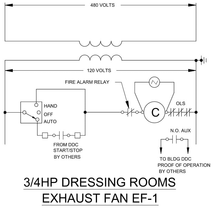
FIGURE 1: A wiring diagram for a 480-V 3-phase combination starter/disconnect. All images courtesy of McClure Engineering, unless noted otherwise.
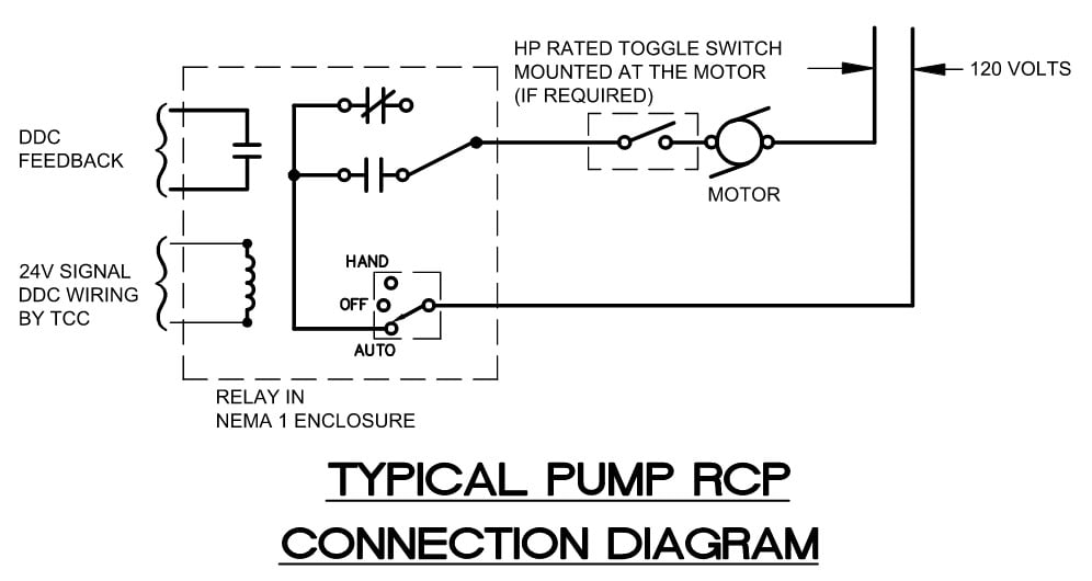
FIGURE 2: A wiring diagram for a 120-V pump with a relay control.
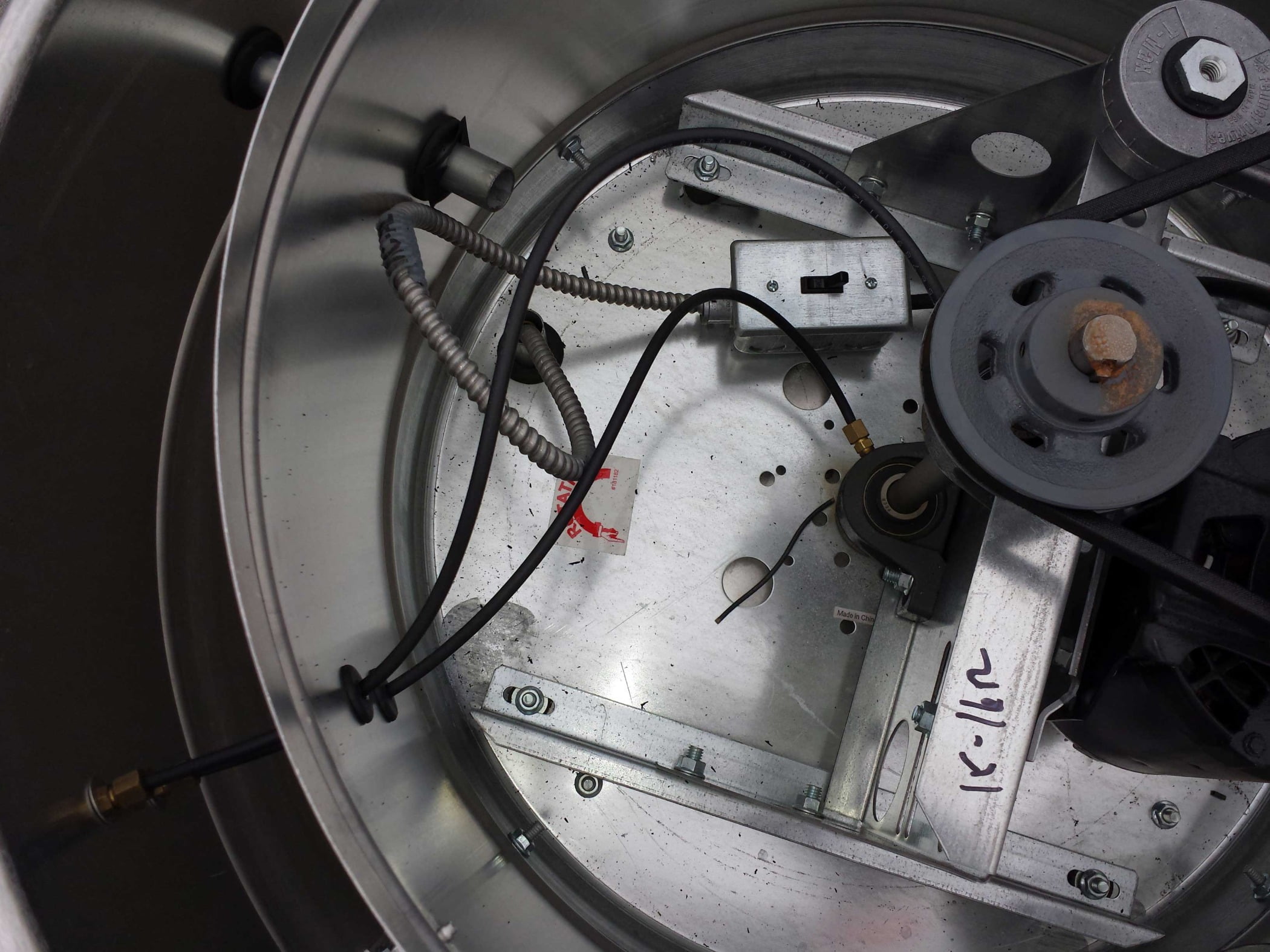
FIGURE 3: An exhaust fan with a PSC motor and belt drive.
Today, life is a little more complicated. Accordingly, ASHRAE published Standard 90, “Energy Conservation in New Building Design,” in 1975. Then, in 1999, the society made significant changes to the standard and renamed it ANSI/ASHRAE/IES Standard 90.1, "Energy Standard for Buildings Except Low-Rise Residential Buildings.” Beginning in 2004, ASHRAE began improving the standard on a continuous basis and reissued the document every three years. The latest version was released in 2019.

FIGURE 4: ASHRAE 90.1 is widely recognized as the worldwide standard for building energy efficiency.
This standard now requires a damper for outdoor air intake and exhaust fans. This could be a non-motorized backdraft damper, but, for best practice and greatest efficiency, it would be a motorized damper. Leakage rate limitations are different between motorized and back draft dampers in the standard. Some climate zones require a motorized damper if the airflow is greater than 300 cfm (140 L/s). With a combination motor starter/disconnect and a 120-V exhaust fan, accomplishing this task was easy. Just select a 120-V normally closed damper actuator and energizing the circuit will operate the fan and open the damper. A 480-V air-handling unit with outdoor air damper might be controlled by combination a starter/disconnect where the 120-V control circuit actuates the damper.
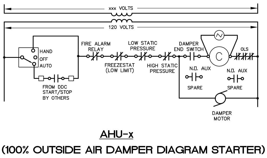
FIGURE 5: A 480-V combination starter/disconnect wiring diagram with 120-V damper control.
FIGURE 6: A roof exhaust curb with a hinged fan base and gravity back draft damper in the curb. Power wiring is implemented through the curb corner.
Today, we select an exhaust fan with a direct drive electronically commutated motor (ECM) for greater reliability, greater efficiency, and less maintenance, so a combination starter/disconnect is not required. Overloads are no longer needed, as the ECM’s internal rectifier converts the AC current to DC voltage at the motor. A motor starter is not necessary due to the built-in motor protection, but if the control features of the starter are desired, then one can be supplied. The internal rectifier is usually mounted on the end or side of the motor; however, there is an option to mount this hardware remotely, inside the building instead of on the roof. There is also a speed potentiometer at the controller or exhaust fan motor to set or balance the fan to the required airflow rate (in a constant flow application). If variable speed or variable flow is desired, a controller may be added to the end of the motor, and an input speed control from the building management system (BMS) can control the speed. Some ECMs require line voltage for the motor (120, 208, or 277 V) and separate line voltage for the controller (120 or 24 V), in addition to the control (0-10 V, 24 V PWM). If a damper actuator is desired, a transformer may also be mounted with the control board on the end or side of the motor to supply power to the actuator via a built-in auxiliary contact. The transformer is an option for all roof exhaust fan manufacturers but must be specified. Most speed controllers for each ECM brand are proprietary.
It may be recommended that surge protectors be used because of the solid state controls that control the ECM.
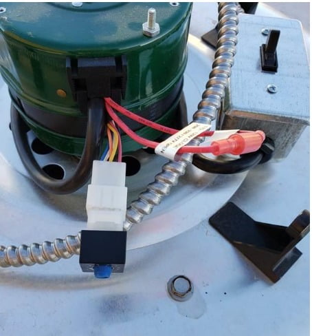
FIGURE 7: A roof exhaust fan with an ECM and constant-speed pot.
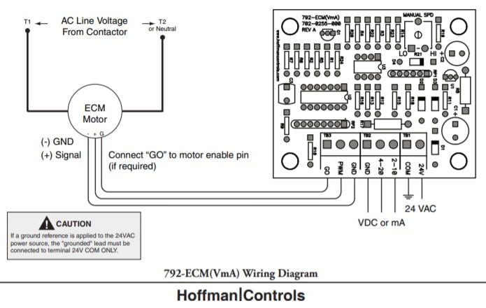
FIGURE 8: A manufacturer’s wiring diagram for an ECM controller. The controller does not have a damper control option²
It is important to note that an ECM operating BHP and motor nameplate HP cannot be directly compared as in a belt drive fan.
Troubleshooting ECMs takes on a new set of steps and differs from troubleshooting older permanent split capacitor (PSC) motors. First, confirm proper system line voltage is connected; second, check for proper high voltage and ground at the (L)(G)(N) connections at the motor. (Some ECMs may field change horsepower settings by altering the pin connections on the motor). If the controller is so configured, confirm there is a 115 or 24 VAC on any one or all of the high-voltage signal connections. Finally, a proprietary inspection tool may be required to test and inspect some ECMs. An ohm meter is required to test the motor. Disconnect the controller and perform a winding test by measuring resistance between each of the three motor leads to the unpainted part of the x-brace. The motor passes the winding test if the meter indicates greater than 100,000 ohms. Next, perform a phase-to-phase test by measuring the motor phase-to-phase resistance by checking these combinations of the three-pin motor connector with an ohm meter: lead 1 to lead 2, lead 1 to lead 3, lead 2 to lead 3. Resistance values should be less than 20 ohms, and each of the three values should be the same (plus or minus 10%). If the measured resistance is outside of these parameters, the motor fails the test. (Verify these values are applicable to your specific motor and controls.)
Are we setting ourselves up for failure by placing all of these electronic components in a roof exhauster? Some manufacturers indicate an acceptable temperature range for the controller board between freezing and 100°F. A roof exhaust fan in most areas of the U.S. will see wider temperature ranges. If we choose to mount these components indoors, then it is necessary to confirm that wiring does not exceed the allowable distance between the controls and the motor. It is also necessary to confirm the quantity and size of the wiring between the controls and the motor. Consider also the need to specify a custom enclosure that houses the components inside (controller, transformer, auxiliary contacts, etc.) and properly label the enclosure. To date, I have not seen an exhaust fan manufacturer list an option for an indoor control enclosure panel. Differences between manufacturers mean there is potential for change orders during construction, as selections are made and designs are laid out based on a manufacturer’s specific components and connection requirements. The temperature control contractor needs to know if he will be terminating inside the roof exhauster or inside a control enclosure indoors.
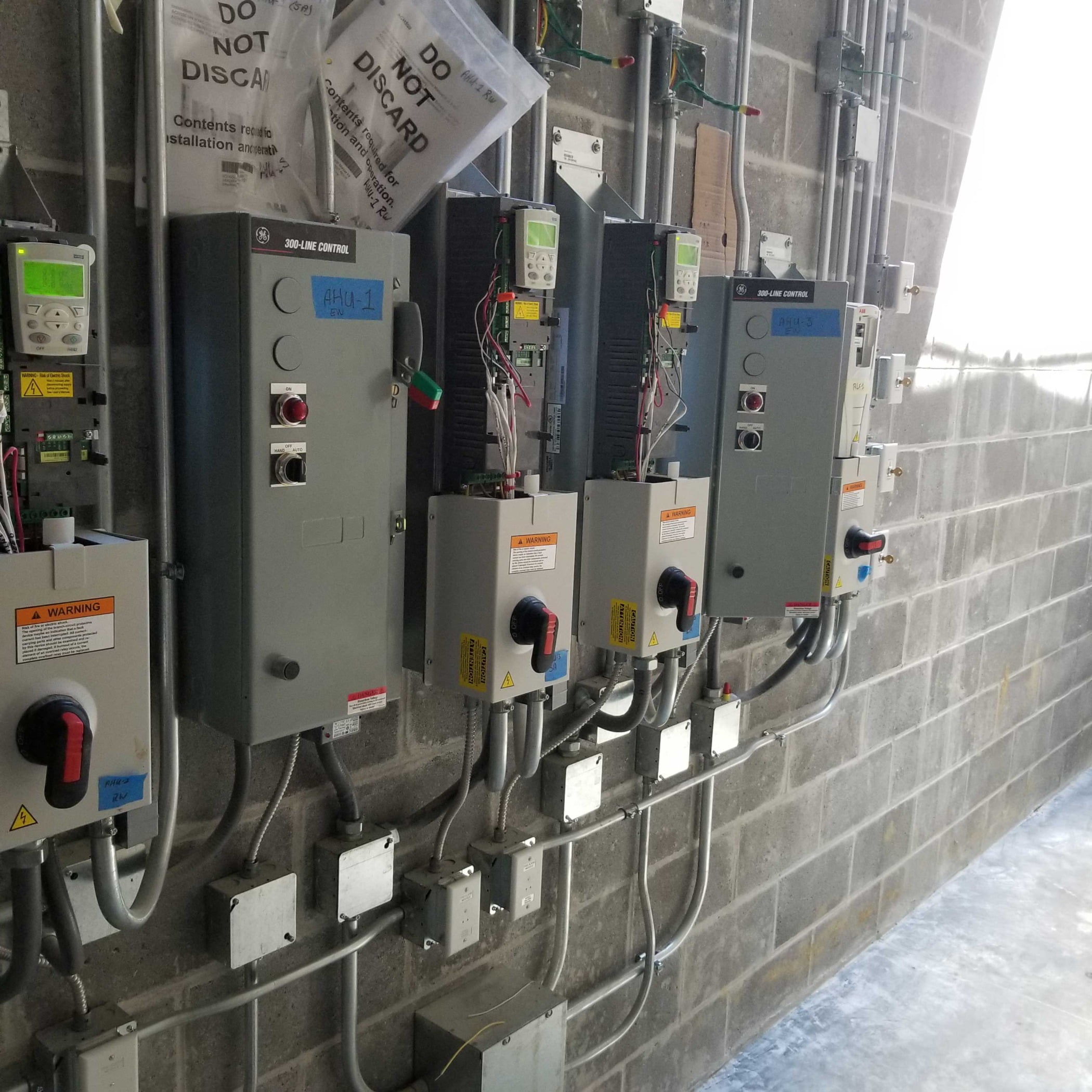
FIGURE 9: Wall-mounted VFDs and combination starter/disconnects may be replaced by ECM remote control enclosures and disconnects.
Other motors may remain PSC type, such as heating water circulators. Sometimes, these circulators are located in a piping cabinet in the rooftop unit they serve. Installation of these circulators are critical and manufacturer-specific, as most require the motor shaft to be horizontal. The motor will ship mounted to the pump but may require rotating to get the electrical connection properly oriented.
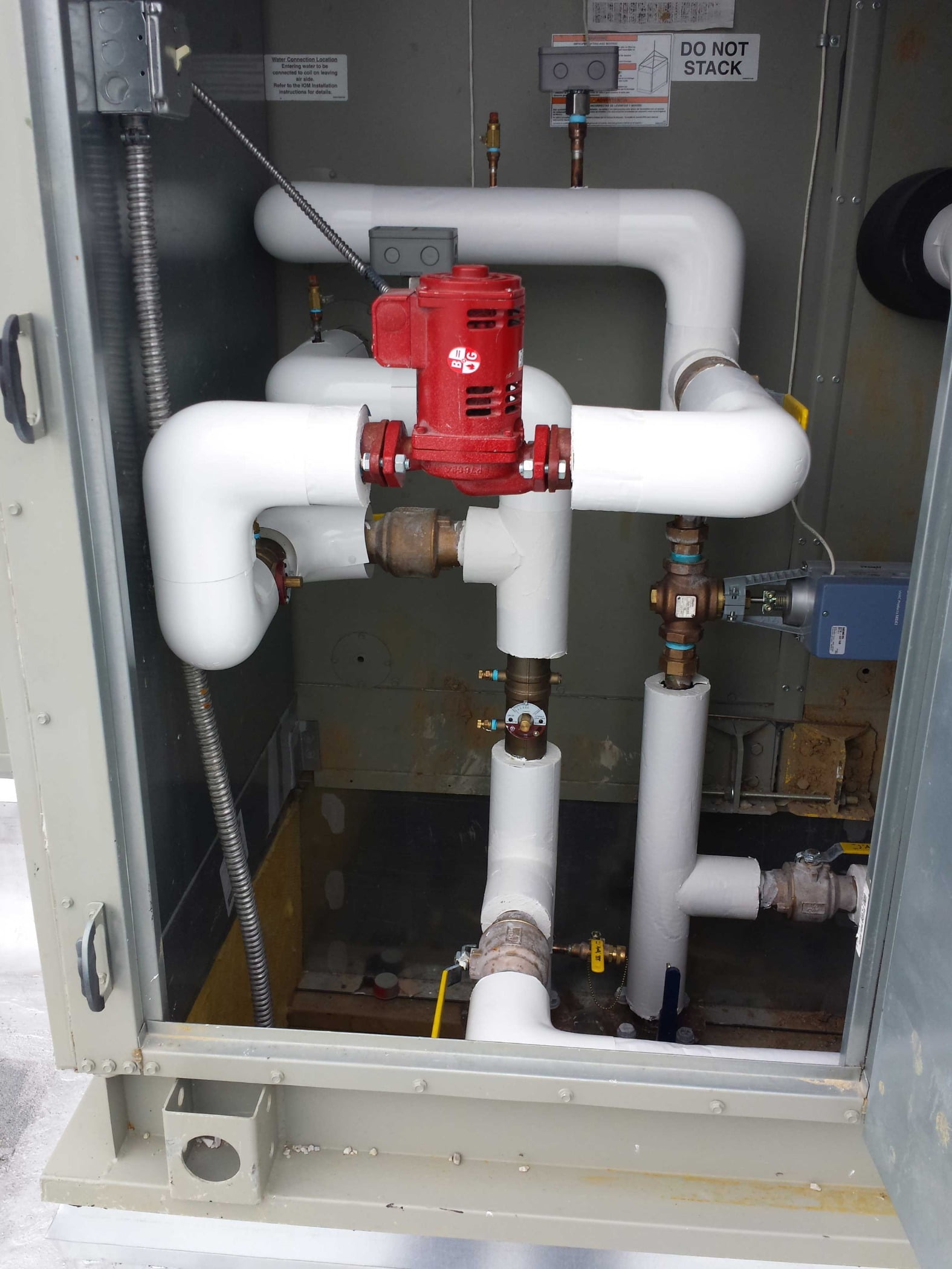
FIGURE 10: A heating coil circulator installed in a rooftop unit’s piping cabinet. The metal-clad (MC) cable between the disconnect and motor is a little short.
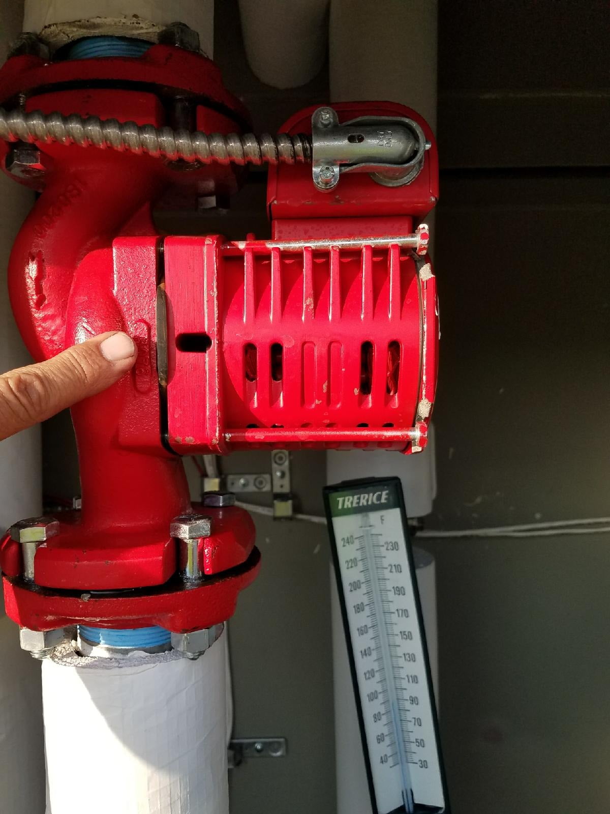
FIGURE 11: A circulator pump with failed mounting flange after the rotation of the motor.
Relay in a box (RIB) relays are still a good way to control constant-speed motors. Applications include hot water return pumps, coil circulating pumps, etc.
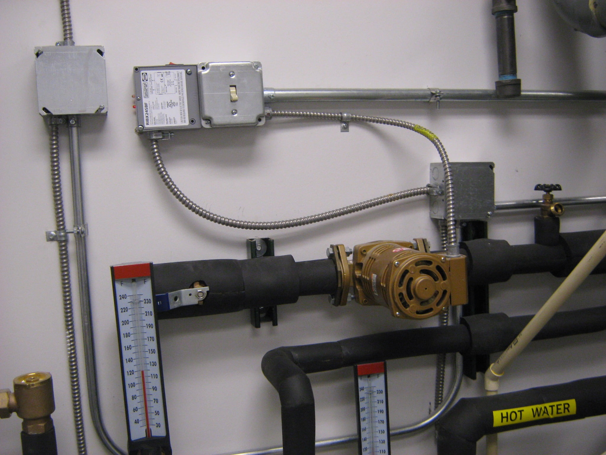
FIGURE 12: A domestic hot water circulator with a relay in a box (RIB) control.
Control or isolation valves may also require 120-V power for operation. Some valves are powered open and powered closed, where others may by powered one way and feature a spring return. This is more typical for larger valves, such as condenser water and chiller or boiler isolation valves.
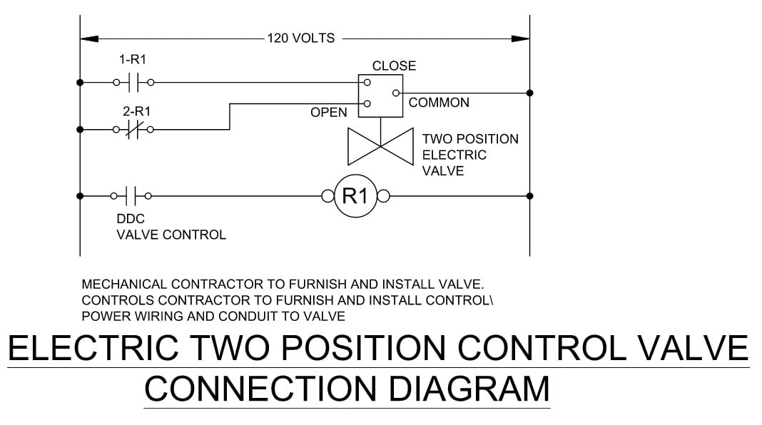
FIGURE 13: A 120-V actuated valve wiring diagram.
Whatever you do, make sure you take pride in your work and install the wiring so that the next guy can follow the wiring and understand the connections. Maybe you can save time on an installation by not needing to cut zip ties to trace wiring, or just maybe it will get cleaned up before the end of the project.
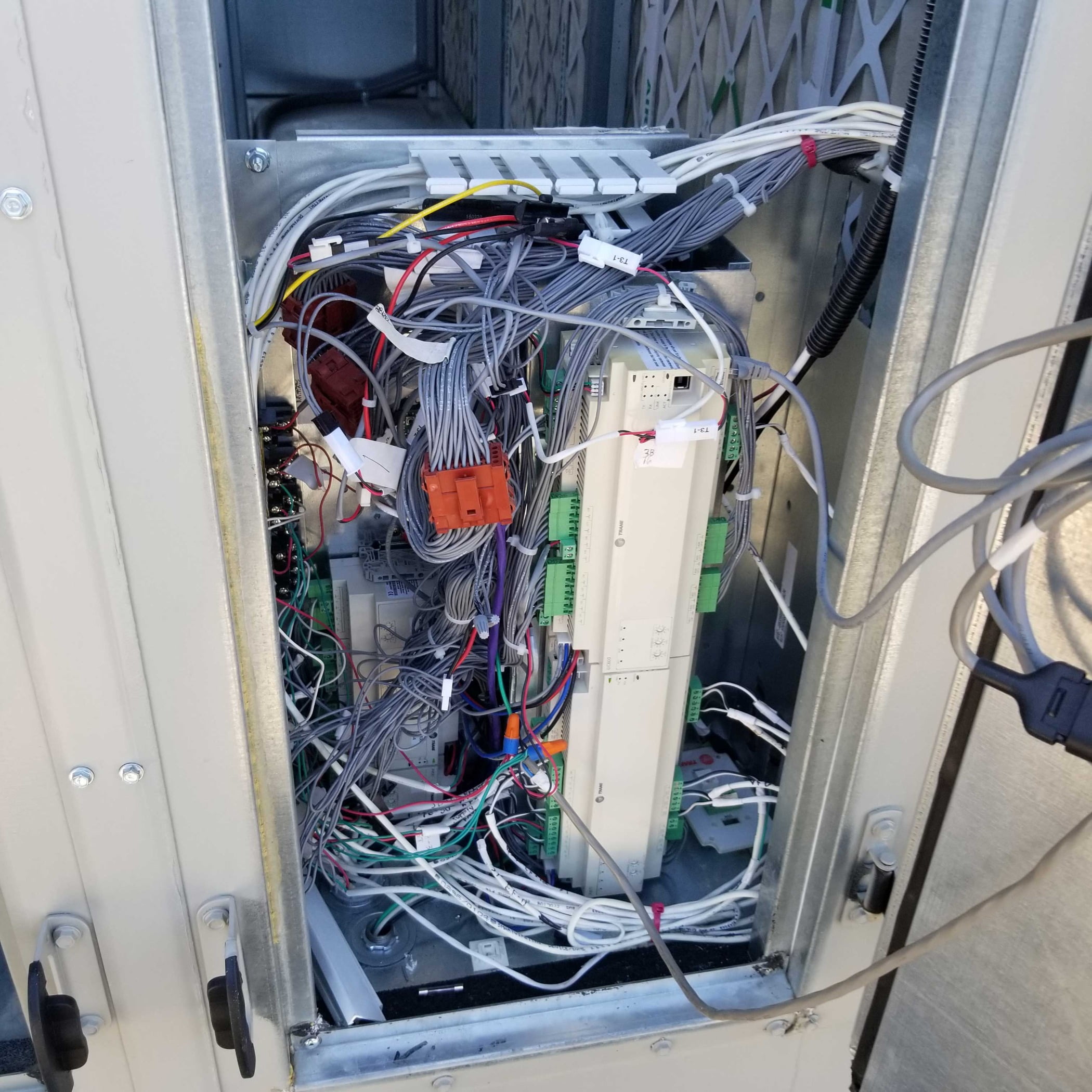
FIGURE 14: A temperature control panel ‘wired’ and mounted inside a rooftop unit cabinet.
Every project will have many wiring details to consider and components to specify. The ECMs are here to stay and will require careful consideration and planning to communicate clear requirements to all trades and the equipment suppliers. Suppliers need to know which accessories are required and if they are mounted on the motor or remote-mounted. The temperature controls contractor needs to know where he is making terminations. The electrical contractor needs to know how many circuits, how many wires, and if he will need to provide custom enclosures for loose-shipped components. One key question may be, “How many packages does this package roof exhauster come in?” Plan carefully young pups and pay attention to the details.
Footnotes:
1. https://control.com/textbook/variable-speed-motor-controls/dc-motor-speed-control/
2. https://www.hoffmancontrols.com/resources/790/791/792/792-ECM_PD_A.pdf