Feature

Gas Turbines:
A Journey
Through Time
The objective of operating a gas turbine is to have efficient compression and expansion processes to produce useable power output.
SCROLL TO VIEW
By Dr. Iyad Al-Attar and Paul Lambart
The history of the gas turbine can be traced back to 150 BC, when a Greek inventor, philosopher, and geometrician, Hero, who lived in Alexandria, Egypt, invented a toy called the “Aeolipile.” The toy was driven (rotated) on top of a boiling pot of water by virtue of hot air flowing in vertical tubes. Although some references consider this engine a gas turbine, Hero, at the time, did not discover a useful purpose for his invention.
Leonardo da Vinci portrayed a chimney jack that rotated due to the effect of hot gases to drive a barbecue spit in 1500 AD. Taqi Al-Adin, in his writings in 1551, described an impulse steam turbine that drove a spit. Giovanni Branca introduced a similar concept in 1629 but with a jet of stream to rotate a turbine, which, in turn, rotated to operate machines.
The contributions continued to develop the gas turbine theory, and, in 1678, Ferdinand Verbiest built a model carriage that used a steam jet for power. Sir Isaac Newton (1687) formulated the three laws of motion, which formed the basis for modern propulsion theory. The Swiss mathematician Leonhard Euler (1707-1783) analyzed Hero’s turbine and conducted experiments with his son, Albert, around 1750. He published his application of Newton’s Law to turbomachinery, known now as Euler’s equation, which enabled a more scientific design approach (1754). The first patent for a basic turbine engine had to wait until 1791, when John Barber designed a horseless “propelling carriage” that included a reciprocating gas compressor, a combustion chamber, and a turbine. Although nothing practical came out of this patent, Barber was the first to provide detailed knowledge of the principle of the gas turbine, and, in 1792, a working model based on Barber’s specification was built and displayed at the Hannover Fair in Germany. Barber’s concept was thorough, but given the technology of the day, it was not possible for the device to create sufficient power to both compress air/gas and produce useful work. Nevertheless, references suggest that the credit for the idea led to the modern gas turbine could clearly be given to Barber.
The influence of Ferdinand Redtenbacher’s (1860) books on the theory and construction of a turbine led Franz Stolze (1872) to design a “fire turbine.” References suggest that Stolze designed the first true gas turbine engine, as the illustration he submitted for its patent was undeniably close to the modern configuration. His axial engine used a multistage turbine section and a flow (few-stages) compressor, which had inefficient diffusion. This engine never ran under its own power. Aegidius Elling’s (1864-1949) attempt to solve Stolze’s problem rested in his proposal for a centrifugal compressor, and his design was the first gas turbine with excess power (1903-1904). In 1897, Sir Charles Parson patented his steam turbine that was used to power a ship, and, in 1914, Charles Curtis filed the first application for a gas turbine engine. Sir Frank Whittle in England (1937) described in his patent a jet engine operation that ran on fuel used for jet propulsion. The list of contributors extends to recent years, and references offer an abundance of attribution to many great people who made power possible and available.
Centuries of development
Although the theory of gas turbines and their anticipated functions were established over the past four centuries, the manufacturing of a gas turbine was faced with great challenges. The shortage of required materials impeded the full implementation of the theory into practice. The gas turbine operation requires components capable of sustaining excessive temperatures for an extended period. Further, additional challenges, such as the growing power demand and fuel price, have highlighted the importance of efficient gas turbine performance.
The definition of gas turbine
The term “gas turbine” describes an engine consisting of at least a compressor, a combustion chamber, and a turbine. It can convert natural gas or other liquid fuels into mechanical energy. In the land-based application, the generated power then drives a generator that produces electricity. Land-based gas turbines are of two types: (1) heavy frame engines and (2) aero-derivative engines.
Figures 3a & 3b
Figures 1 & 2
Working principles
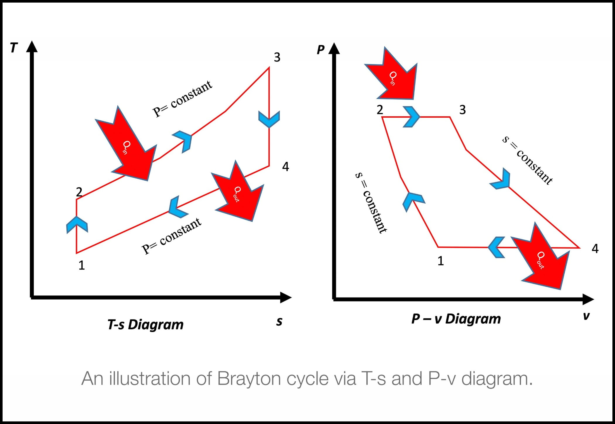
The working principles of a gas turbine are based on the thermodynamic principles of the Brayton cycle as shown in Figure 1. The objective of operating a gas turbine is to have efficient compression and expansion processes to produce useable power output.
Atmospheric air is drawn through a filter housing installed at an elevated level and then passed through the filtration stages prior to entering the compressor via the bell mouth. Filtered air is compressed to high pressure and temperature before entering the combustion chamber where fuel is injected and combusted at constant pressure. The gases that leave the combustor at high temperatures contain large amounts of energy. Energy is then extracted from the hot pressurized gas, thus reducing pressure and temperature. Fifty to 60% of converted energy is used to drive the compressor, and the rest drives a generator or shaft to produce power for the mechanical equipment of interest.
Preparing for a new era
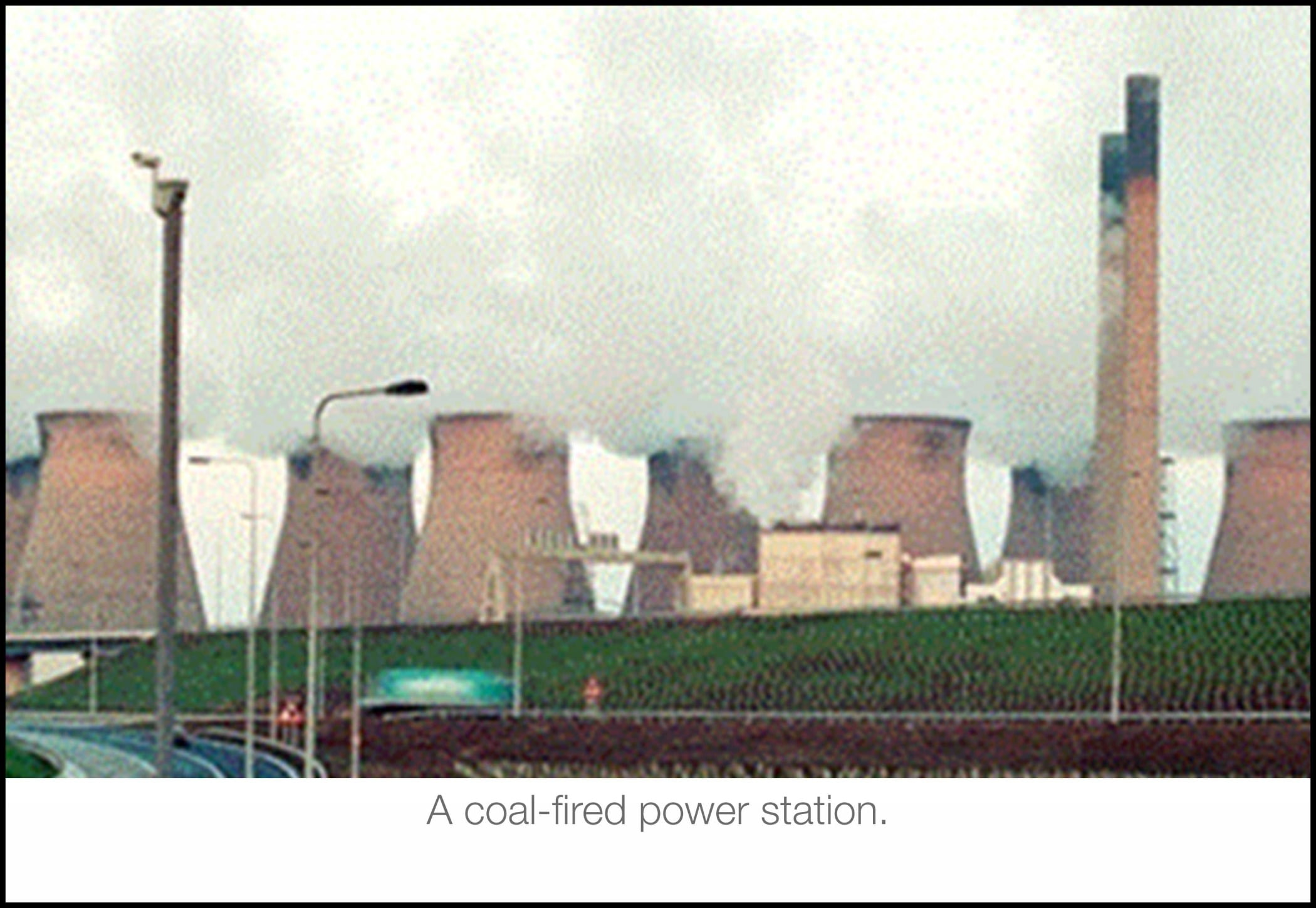
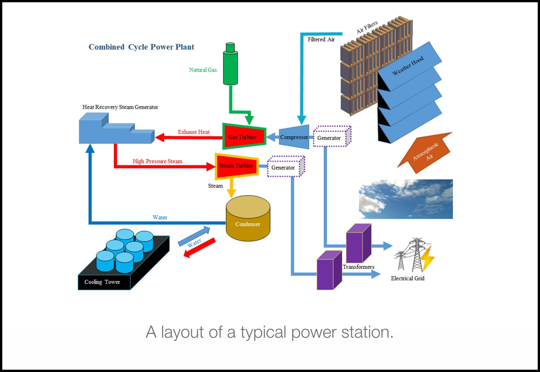
First, some historical background. Power generation from fossil fuels has long since been the preferred method. Initially, coal was burnt to produce steam that could power turbines that, in turn, would drive generators to produce electricity supplied to the grid (Figure 2). This process made electricity cheap, as the power stations were typically located close to the source of coal, making transportation economical. However, as with most processes, there are always drawbacks, and the most significant ones in this case were the smoke, smog, waste heat emissions, and thermal efficiency of around 35%.
As oil and gas became more readily available in the mid-20th century, a complementary generating process became available in the guise of the gas turbine. Here, oil or gas were combined with the air that was compressed to some 15 bar pressure in combustion chambers, the resulting exhaust gas was then used to spin the turbine that, in turn, powered the compressor and the generator. Since this process used some 50% of the turbines energy to drive the compressor, it was quickly identified that the waste heat from the combustion process could be used to raise steam that could drive a steam turbine downstream of the gas turbine, thus increasing the thermal efficiency from some 34% to over 50%. Another benefit of the gas turbine is its flexibility in terms of how the load can flex to meet demand and even rapid stop/start cycles. For sure, that is much more difficult with coal-fired power plants.
The popularity of gas turbines has spread around the world, and, in the oil-rich countries of the Middle East, they are the main stay of generated power. But they can and do operate in many different environments and temperature ranges, all of which impact the operational output and efficiency.
Gas turbines are rated for performance by their manufacturers to ISO (3977) conditions, which are 15℃ and 101.3 KPa. If we consider an ISO-rated gas turbine of 100 MW installed in a desert environment of 50℃, we could expect its output to be reduced by up to 25%. Therefore, when comparing the performance of gas turbines, it is normal to adjust the output figure to ISO 3977.
Figures 5, 6, 7
Figures 4a - 4f
Gas turbine performance influencers
The performance of all gas turbines is affected during operating because the air being consumed contains airborne particles that will affect the performance in a variety of ways. One of the most readily available indicators of losses in gas turbine performance is a drop in output, either mechanical or electrical, depending upon the installation, although this can sometimes be overlooked, especially if the gas turbine is not operating at part-load conditions rather than at base load. This is because when at part-load, a gas turbine has a degree of flexibility within the operating parameters and limitations to meet the demand placed upon it by increasing the fuel flow or permitting a higher exhaust gas temperature to suit the situation. Whilst this allows the gas turbine to continue to operate, the full impact of the degraded performance may not become apparent until weeks or even months later at an outage.
An alternative method, which requires some calculations, is that of compressor efficiency. The losses experienced can be split into two groups, recoverable and non-recoverable, and affect various sections within the gas turbine in different ways. Recoverable losses can be regained during normal operations. The main type, due to compressor fouling, is usually rectified by carrying out a compressor wash; this can be either online, whilst the gas turbine is operating, or offline, when it is shut down. Non-recoverable losses are due to both the normal wear of internal components, such as blade tips that increase the tip clearance, and also to the ingested material that causes erosion or corrosion.
The damage that the impact of airborne particles in the airflow causes to the compressor blades is called erosion and alters the aero foil profile of the blades thereby changing it from the design point. These changes can be a reduction of the blade chord, which shortens the blade length. This, in turn, increases tip losses, blunting the leading edges and sharpening the trailing edges.
Corrosion, on the other hand, is induced by contaminants that adhere to, and react with, the material of the blades, which will lead to pitting of the surface. This causes roughness and disruption of the airflow, which could ultimately lead to failure of the equipment due to localized stress points.
The challenges ahead
Now that we understand a little of the history of gas turbines, their benefits of operation, and the consequences of not looking after them, let us look to the future.
As we have already stated, gas turbines operate in different environments, such as tropical, coastal, industrial, and desert climates. They also need to deal with a wide array of atmospheric contaminants with various concentrations and particle size distributions.
In this new century, should we ask ourselves if there is a place for gas turbines when we are constantly asked to focus on renewable energy? We understand a great deal about the operation of gas turbines, and, with some consideration and adoption of new technologies, perhaps they can help us buy some time until we can establish a true zero carbon footprint and hydrogen economy.
A gas turbine is at its most efficient when it is operating at base-load conditions, which is full power. Although it takes away some of the engine’s flexibility, it means the engine is producing less emissions than at a part-load setting. If we then ensure we can provide an in-let filtration system that is designed for the specific environment in which the engine is operating, that system will not impede the flow of air into the compressor. Add to this the concept of keeping the compressor clean and free of potentially damaging fouling, and we have an engine that is operating close to its peak performance.
If we then address the way that we handle/treat the emissions from the exhaust, all of a sudden, we have sustainable operation capable of producing large amounts of power.
Of course, it could be argued that not all that power is required all the time. If so, why not use the excess power to produce hydrogen, charge batteries, and fill caverns with compressed air?
We simply need to reevaluate the way we use energy in a responsible way. Let’s look in more detail at the influences and technologies available.
Figures 8, 9 , 10
Air filtration
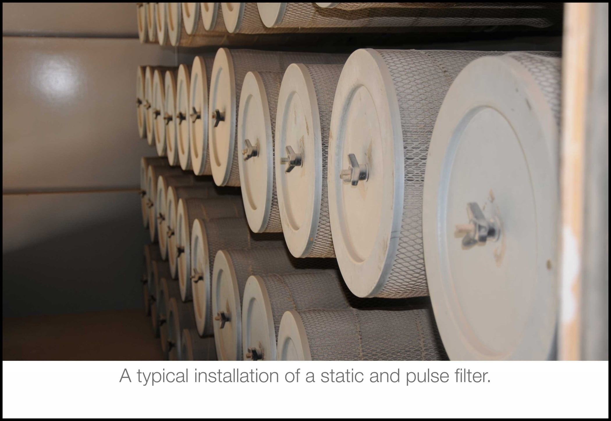
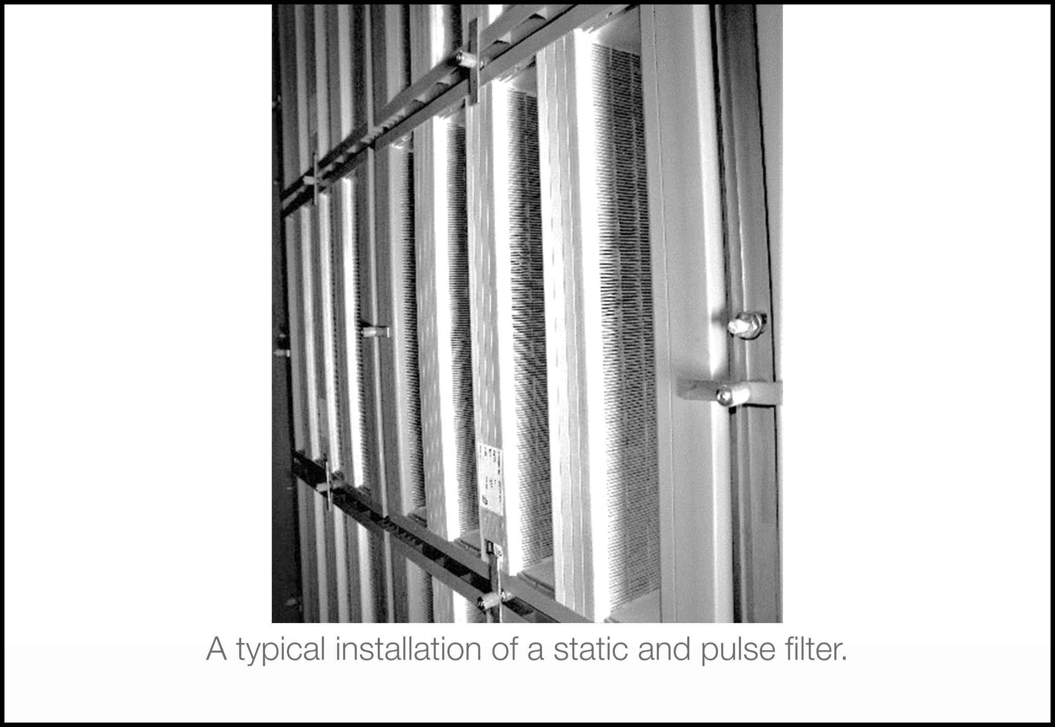
Air filtration emerges as a critical (separation and retention) process to capture pollutants prior to introducing the air to the gas turbine engine. Different filtration techniques, such as static (depth) and pulse (surface) filters, as shown in Figure 3, are employed to protect the compressor assembly from suspended contaminants. Therefore, accurate filter performance prediction facilitates their appropriate selection in order to avoid premature clogging.
This can be facilitated by virtue of capitalizing on multistage filtration selected after professional aerosol monitoring has been conducted. This would allow the engineer in charge to recognize the contaminants the gas turbine engine is up against and make appropriate filtration plans and compressor washing techniques to combat them. Furthermore, the detailed account of filter media must be investigated since it is the building block of the filter cartridges.
Filter loading
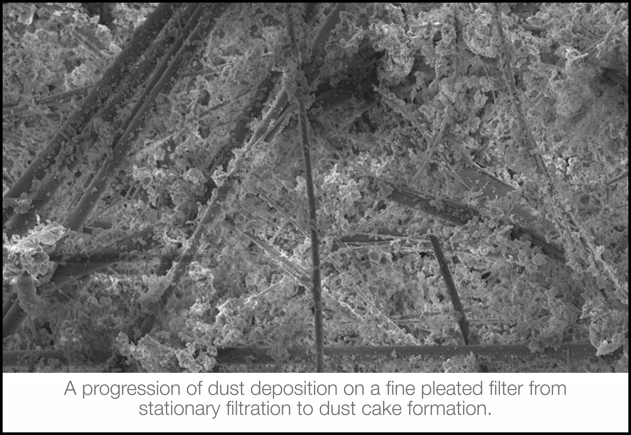
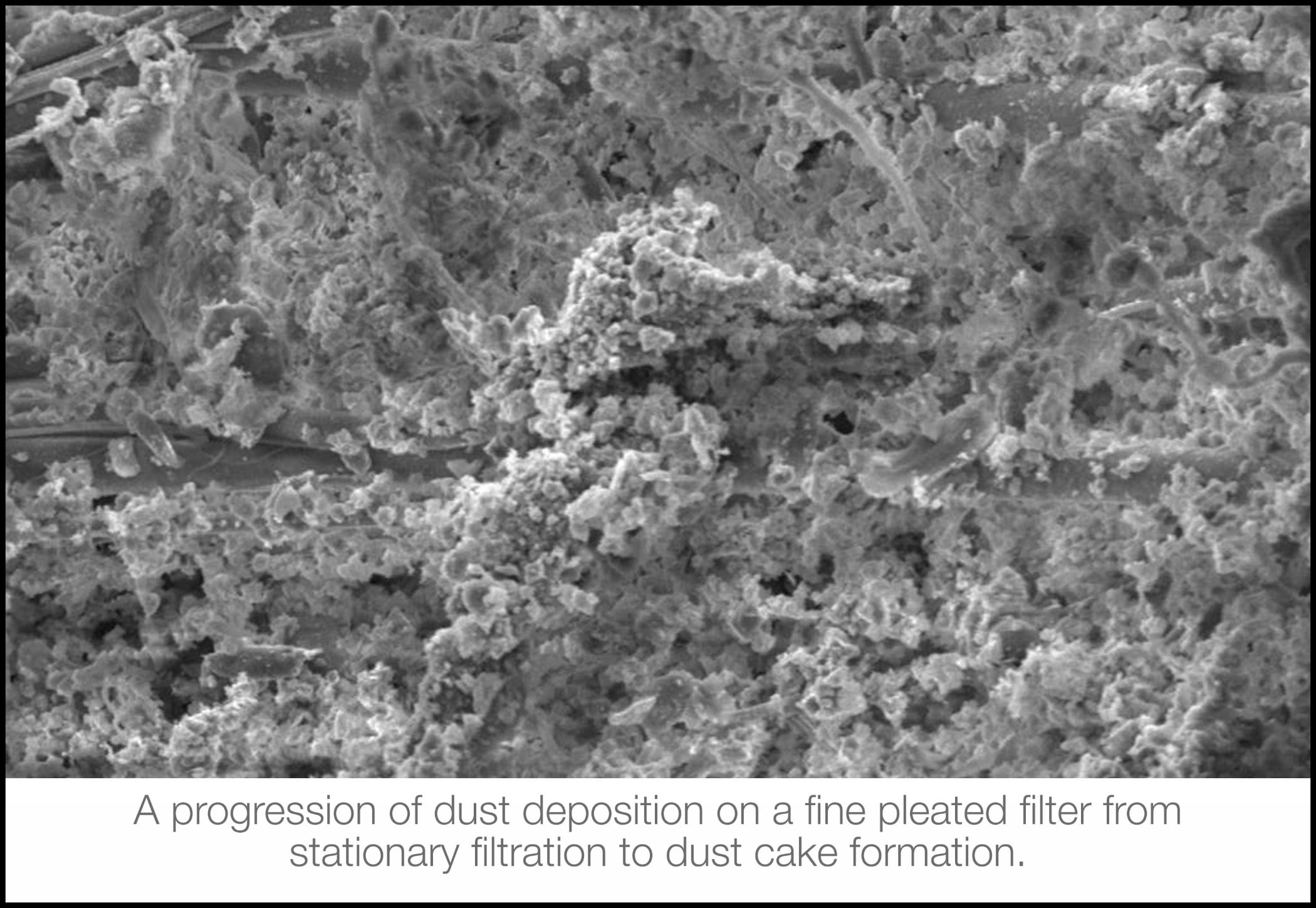
A critical aspect to consider in filter loading is enhancing the efficiency by means of increasing the probability of particle-fiber deposition/capture within filter medium. However, that would require careful consideration of the atmospheric particle size distribution relative to the filter media pore size. If left unpreceded by pre-filters, such exposure of high particle concentration of the atmospheric air can result in surface-deposition and, consequently, premature clogging.
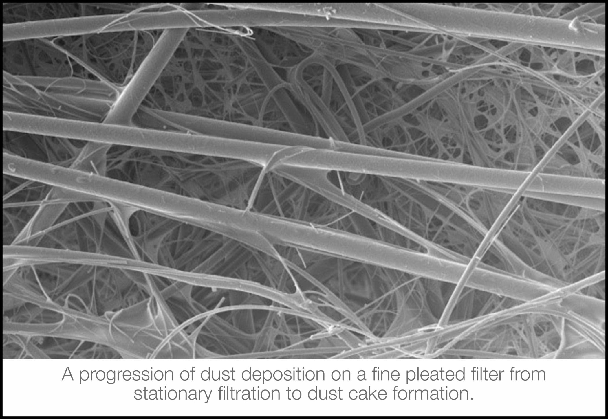
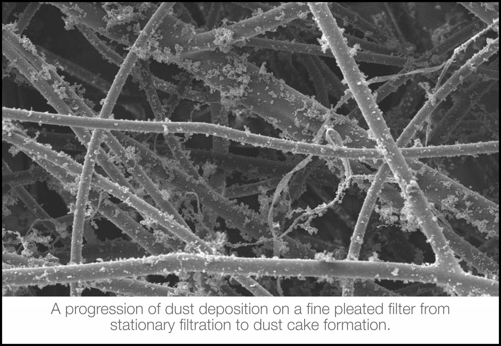
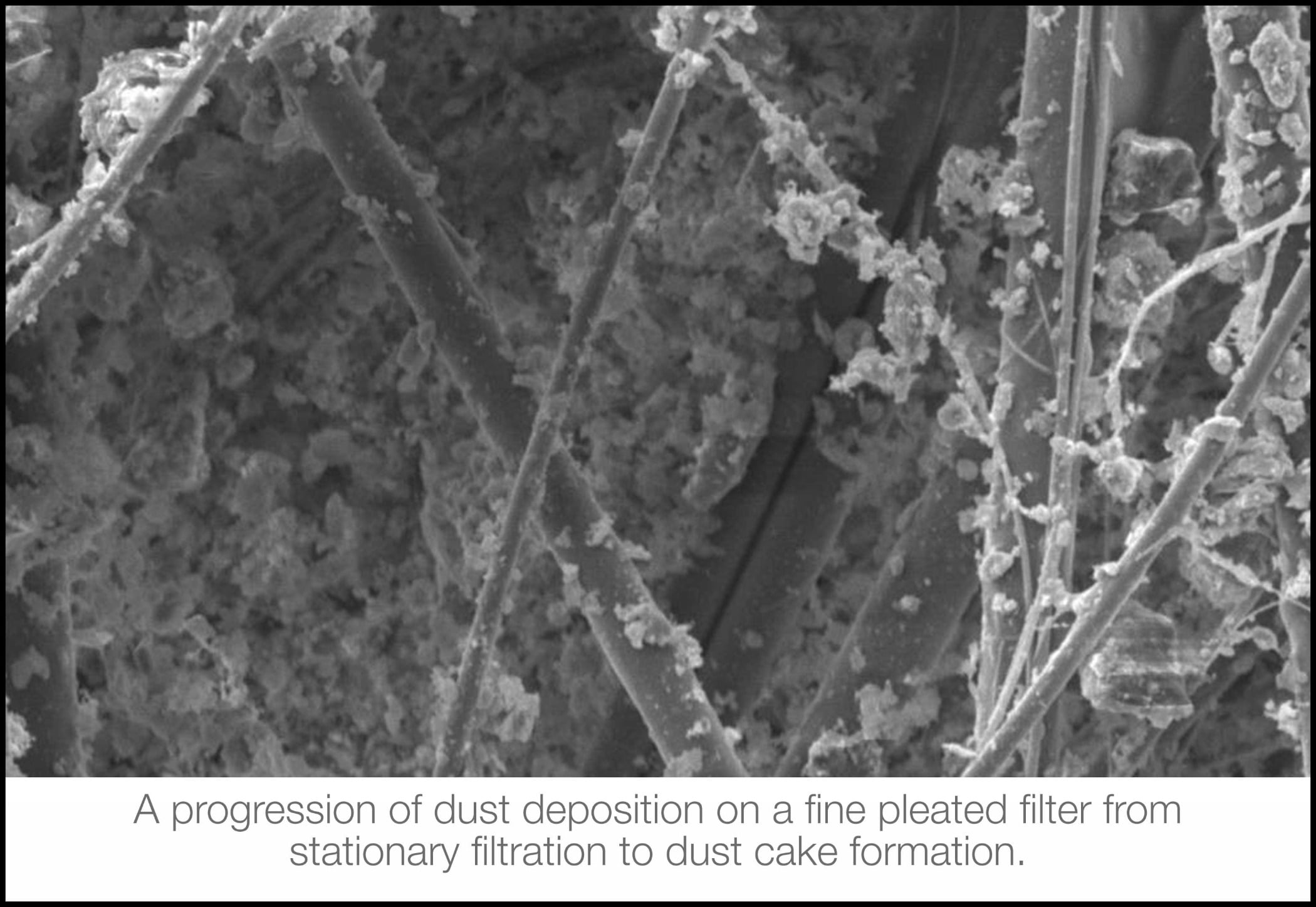
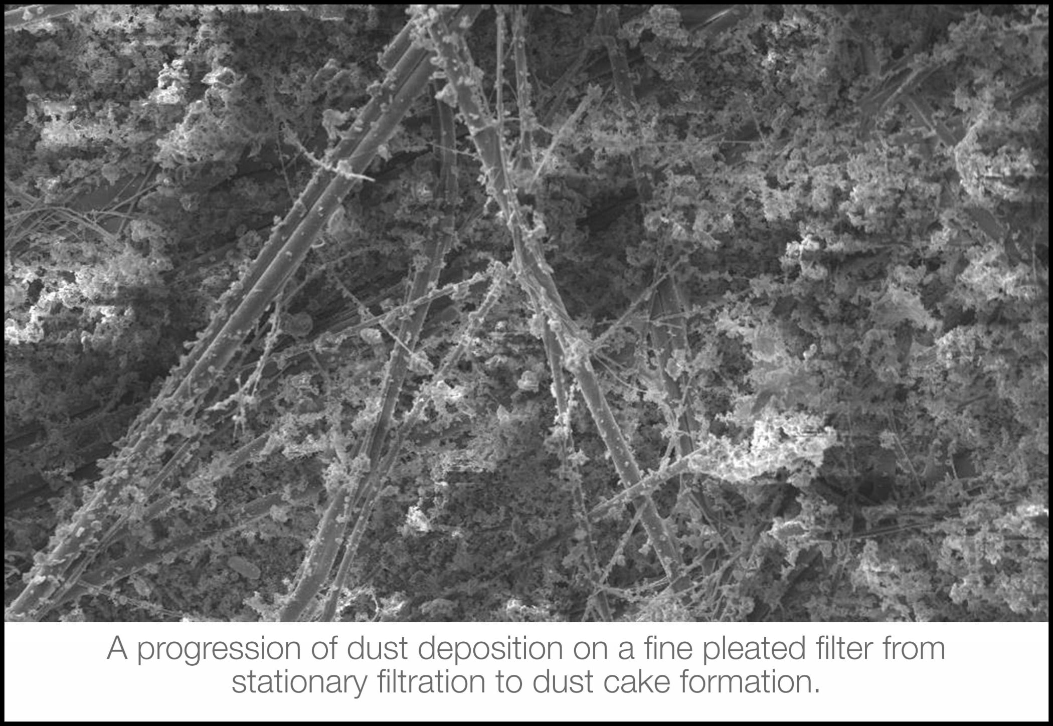
The progression of particle loading challenging fibrous media from stationary phase to nonstationary phase and eventually to dust cake formation is illustrated in Figure 4. The nonstationary filtration occurs when particles deposited around the filter fibers alter the pore structure of the filter media and cause a pronounced rise in the resistance to airflow through the filter, resulting in the filter’s pressure drop.
Improving efficiency
An efficiency improvement as low as 1% is significant to gas turbine operators. Sustained gas turbine performance translates into maintaining the designed power output and reducing fuel consumption, emissions, and number of outages. Therefore, employing effective maintenance measures, such as qualified filtration and compressor washing techniques, are in demand. Operational implications must also be considered in comprehending the underlying issues caused by the inability of air filters to remove all suspended contaminants with various phases, concentrations, size distribution, and/or chemical composition. Clearly, compressor washing techniques are credible candidates in bringing the compressor assembly back to its design point. However, as mentioned earlier, this requires a balanced approach with air filtration performance.
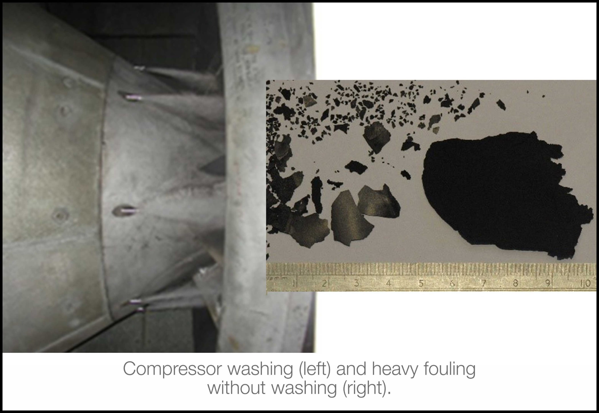
Compressor washing
It is well-established that regular washing of compressor blades is the most effective way to resist fouling and is particularly recommended to optimize a regime of online and offline compressor washing. It is agreed that online and offline washes complement each other and that online washes can slow down the rate of fouling and extend the offline wash interval. To remove this fouling (Figure 5) from the compressor of a gas turbine, a number of methods have been established and made available for the operator. In an effort to restore the performance, they comprise hand cleaning, crank/offline washing, and online washing. A number of these procedures require the gas turbine to be removed from operations, stopped, and cleaned before being returned to service and range from manually cleaning each blade to rotating the gas turbine using the starter motor or generator and injecting the cleaning media directly into the inlet plenum and allowing the airflow to carry it into the compressor section.
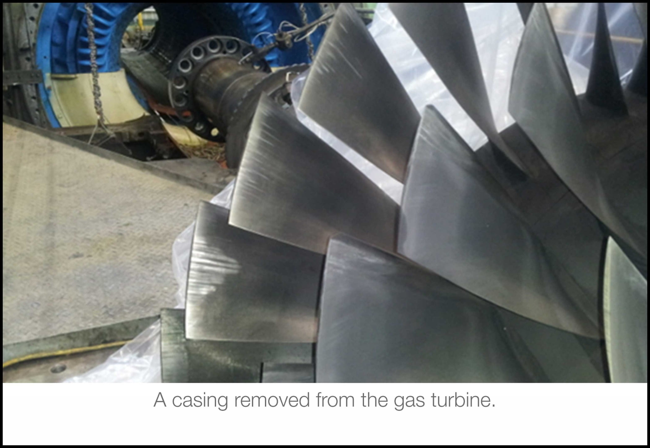
Alternatively, depending on the level of fouling and cleaning media used, the cleaning can be carried out whilst the gas turbine is running at full or part load. Hand cleaning is normally carried out during a major overhaul or when there has been a large loss of performance possibly due to oil contamination, which has exacerbated the rate of fouling beyond acceptable levels. It involves removing the top half casing of the compressor to expose the rotor and possibly removing the entire rotor section, which is not only time-consuming but also very labor intensive and often involves the use of solvent-based cleaners (Figure 6).
Crank washing allows the gas turbine to be rotated without firing at a relatively slow RPM by means of the starter motor or generator. This has an adverse effect on the life of the starter motor or generator by increasing the number of starts per operational hours. Due to slow rotational speed, typically 10% of normal production operations and the unfired nature of operation the conditions experienced inside the compressor are much less severe than normal, which produces the potential for a much more thorough cleaning process and also the ability to use either solvent- or aqueous-based cleaning fluids.
Any performance gain from carrying out an offline wash on a large gas turbine needs to be balanced against the loss of revenue, in particular for the case of a power generator operating a large gas turbine where there is a protracted period needed for cooling to avoid thermal shock prior to the wash, the wash and rinse cycles, and bringing the gas turbine back into service. Studies have shown that each additional start will have an adverse effect on the operating hours and subsequently reduce the interval between maintenance interventions.
Inlet filtration (the balanced approach)
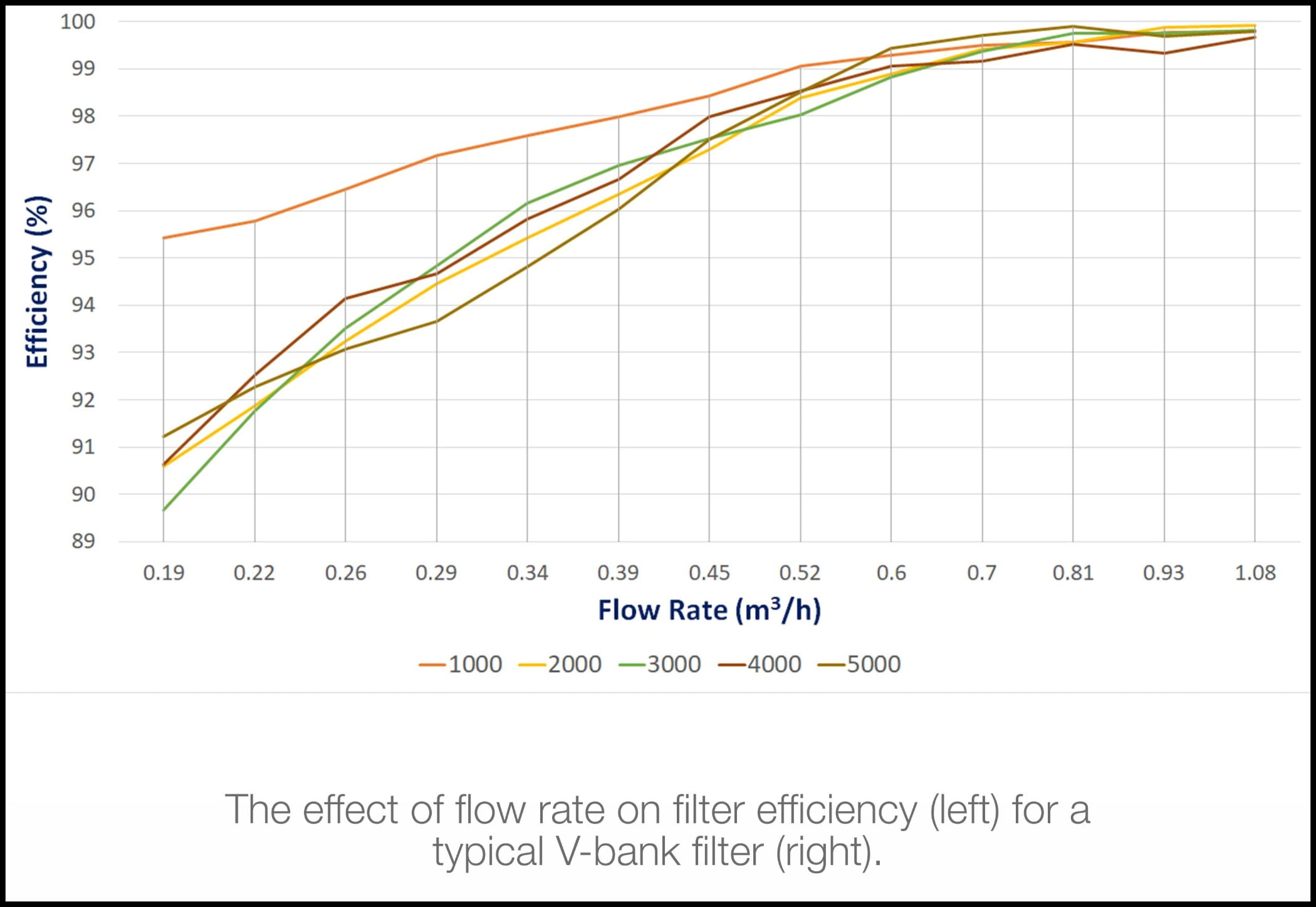
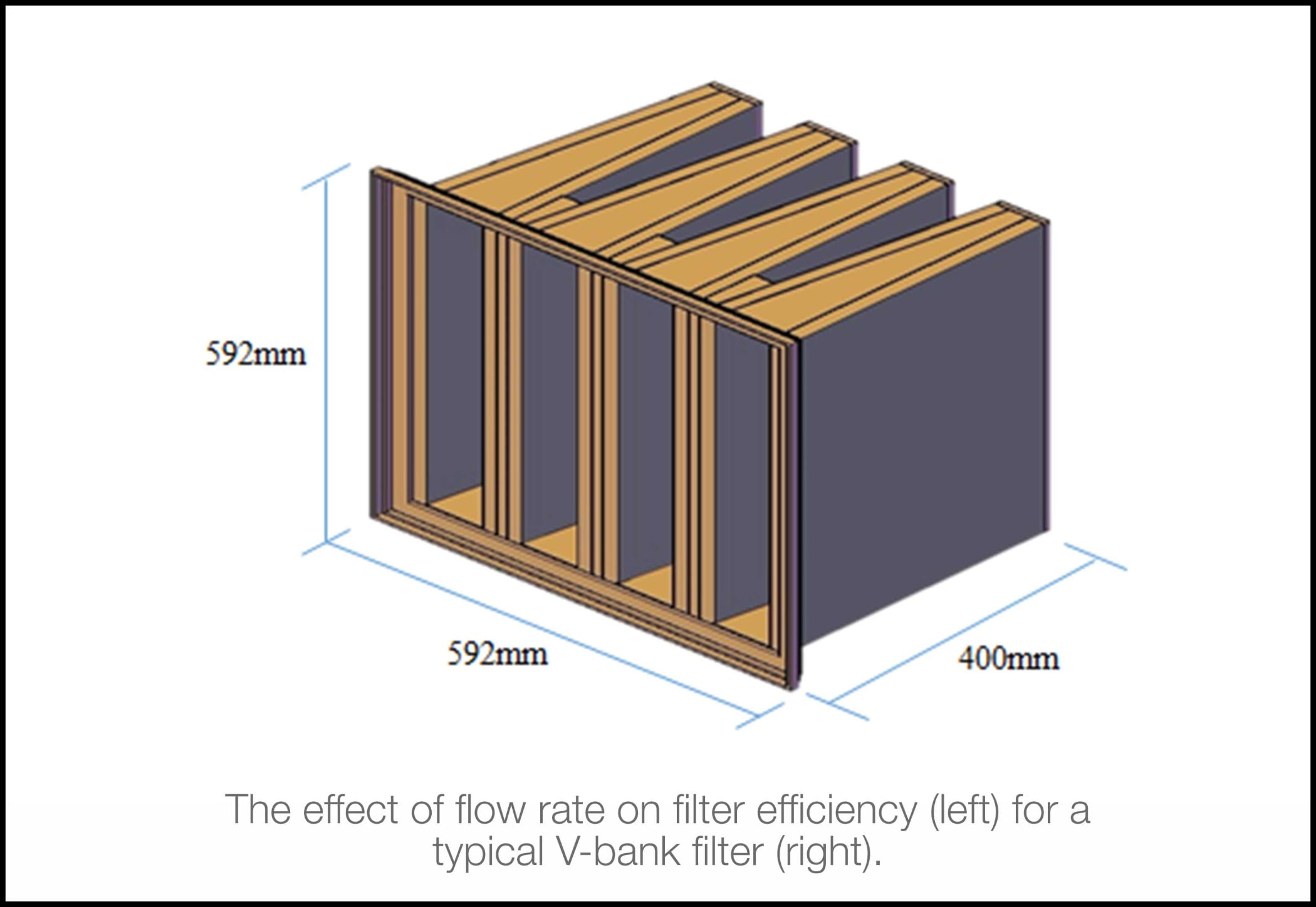
Increasing the number of filter stages and/or upgrading their efficiency leads to pressure drop increase of the entire filter section. On the other hand, reducing the number of filter stages and/or their efficiencies provides greater volume of unfiltered air to reach the gas turbine engine. However, this would subject the compressor assembly to various types and concentration of airborne pollutants deposition to be washed when required. It is also important to realize that flow rate used in land-based gas turbine is higher than that used in HVAC applications. The effect of flow rate on filter efficiency for a typical V-bank filter is illustrated in Figure 7. Clearly, the filter experiences a reduction in its overall efficiency as a result of flow rate increases
Therefore, installed air filters are exposed to greater concentrations of contaminants with various size distribution and chemical composition throughout their life times. Ultimately, the limitations of air filters and the wide spectrum of suspended pollutants make it difficult to rely on air filtration as a sole technique to maintain gas turbine performance. Therefore, compressor washing techniques come in handy in rendering the compressor assembly back to its design point. Perhaps a techno-economic study can reveal the current design limits of both technologies prior to holding them responsible for engine performance degradation. Particularly, since an efficiency gain as low as 1% is significant to gas turbine operators. Sustained gas turbine performance translates into maintaining the designed power output and reducing fuel consumption, emissions, and the number of outages. Therefore, implementing a balanced approach between professional air filter installation and compressor washing techniques can prove invaluable in designing maintenance measures. Clearly, the objective is to utilize available tools to maintain optimum efficiency of the compressor. However, one must address the inability of air filters to remove all suspended contaminants with various concentrations, size distribution, and chemical composition.
Air pollution and sandstorms
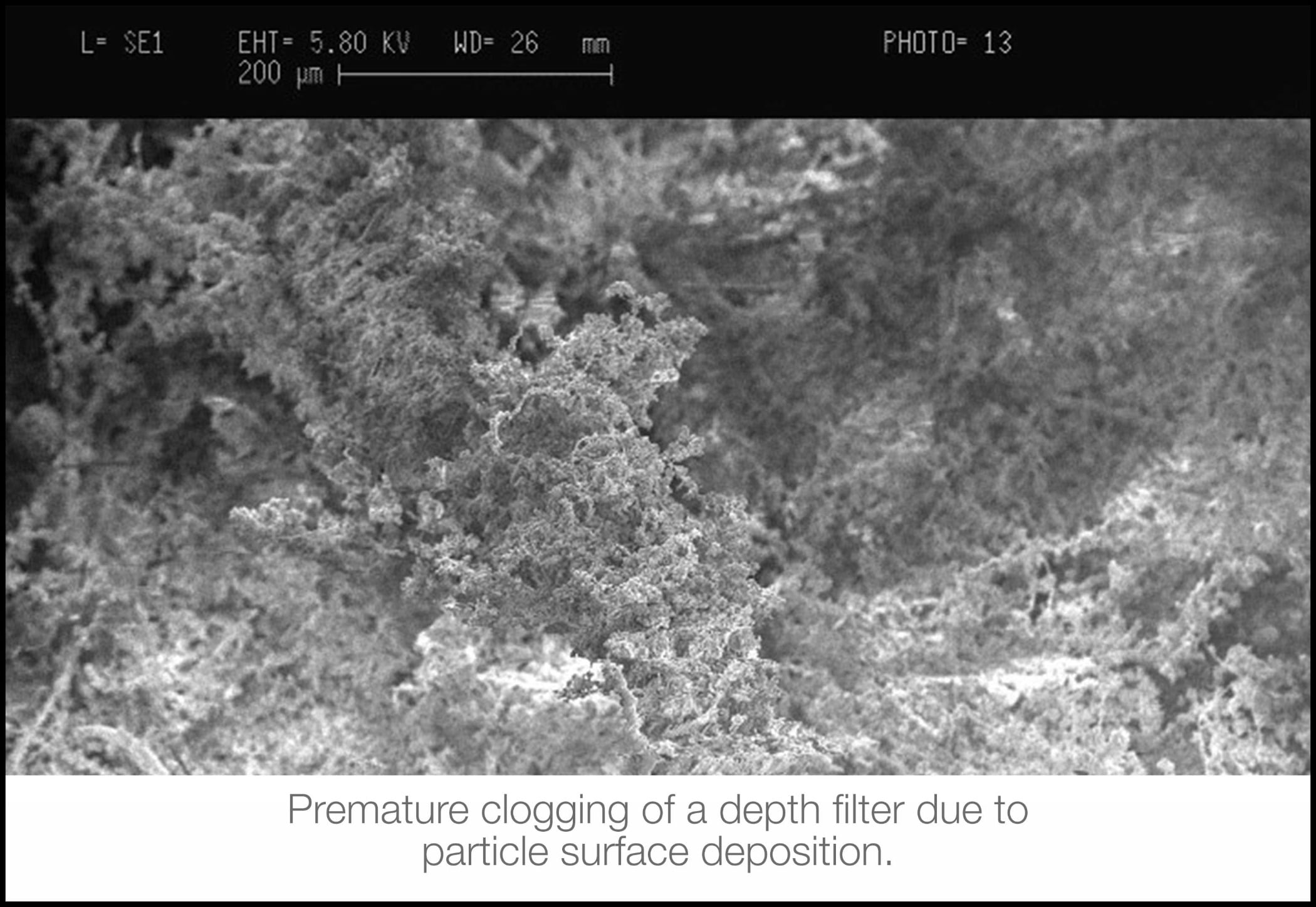
Air pollution and sandstorms add to the complexity of filter performance prediction. Research has proven that polluted air and sandstorms expose the installed filters to high particle concentration, causing them to bridge with one another leading to dust-cake formation whereby particles begin to agglomerate. Furthermore, high particle concentration alters filter porosity and occupies the interstitial spaces of the filter medium, causing a significant rise in the filter’s pressure. Unfortunately, surface deposition occurrence on a depth filter does not warrant the full utilization of filter depth/thickness as shown in Figure 8. It could also reduce filter permeability, triggering premature clogging and more frequent filter replacements because of the accelerated rise in pressure drop.
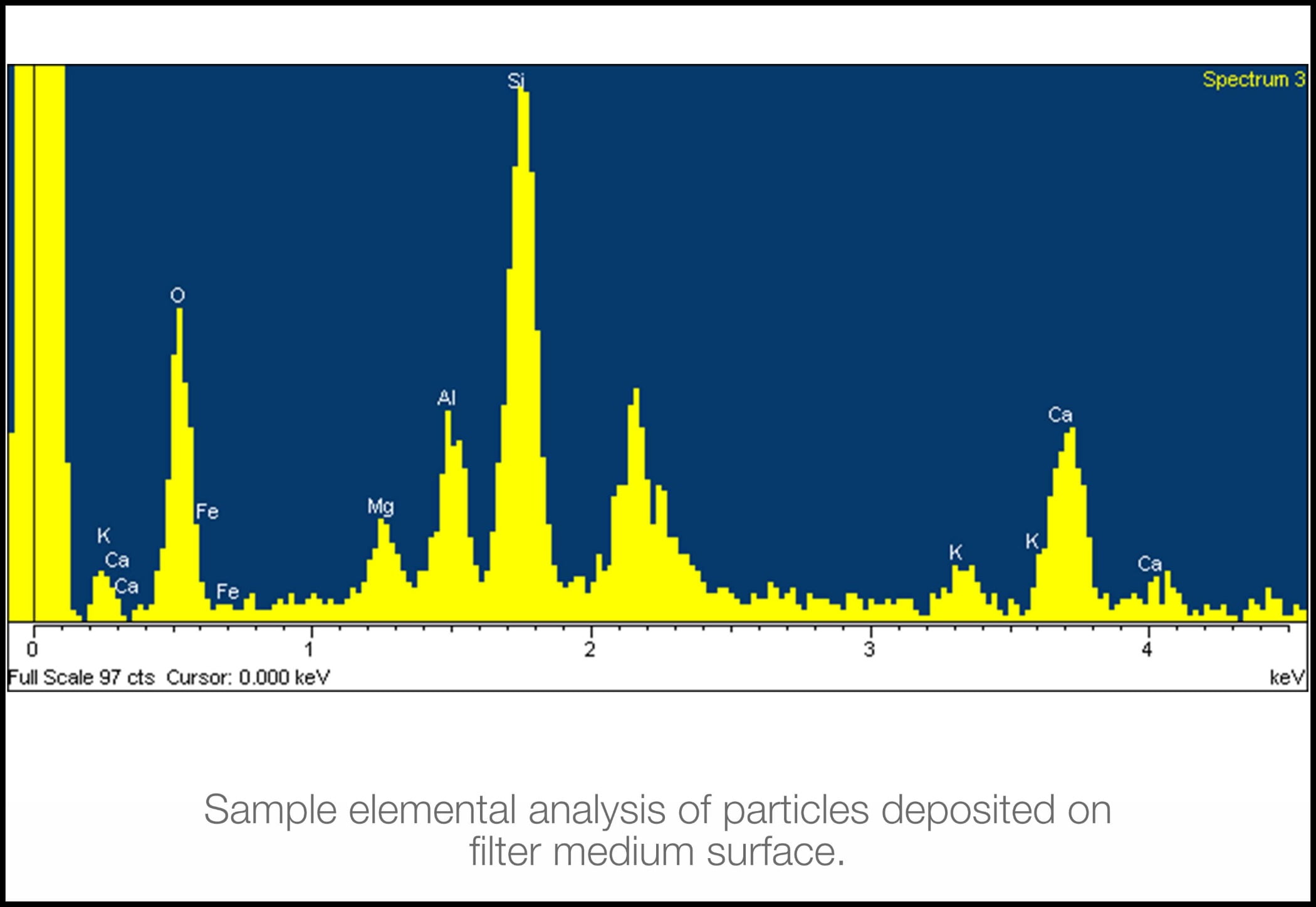
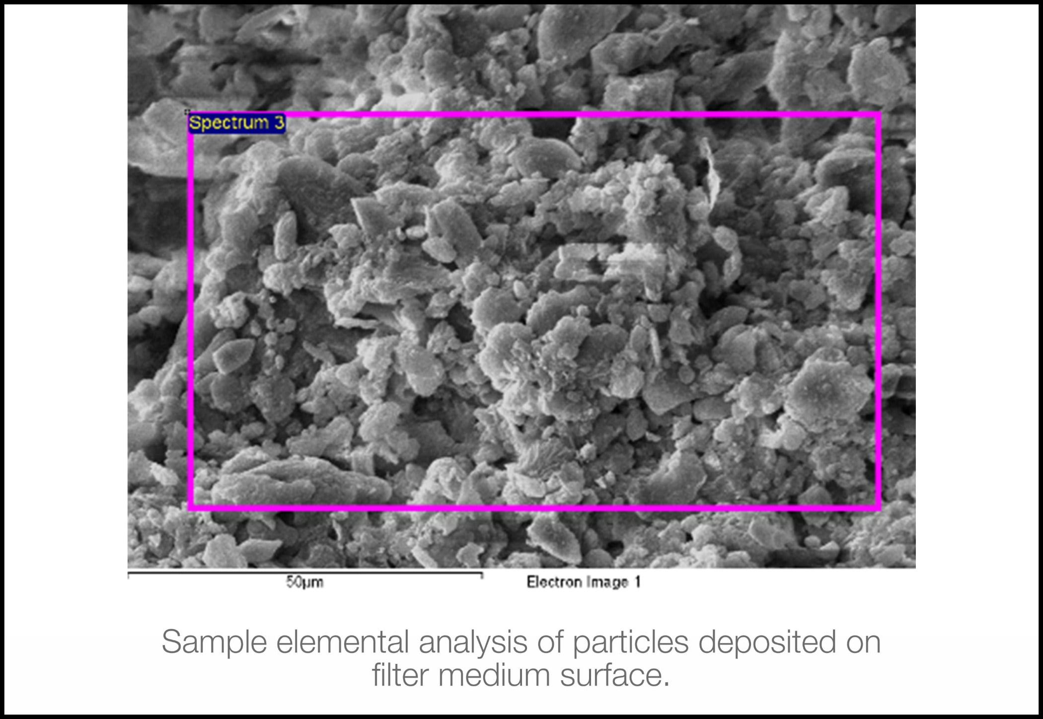
The atmospheric air around the power station has its own characteristics, and it is vital that its chemistry is understood. Certain elements are damaging to some of the gas turbines’ components. Therefore, if they are identified in the analysis, the filtration system must be capable of capturing them. The analysis should also give an indication of the size range of the particles and even the shape (Figure 9).
Combining technologies
If we consider the last two technologies of compressor washing and inlet filtration, it would seem that perhaps there is an argument for them to be combined in some way in which they could support one another. Whatever the manufacturers of these technologies may say, one technology does not supersede the other. Taking two extremes, if you were to employ a massive filter and were prepared to change it every day, you could prevent every last micron of dust from entering the compressor, one would never need to wash it, as the compressor would stay perfectly clean. But you would have such a massive pressure drop across the filters that the engine would have no performance. Likewise, you could remove the filters so there was zero pressure drop and continually online wash any particles that entered the compressor. Of course, you then run the risk of any large particles that were ingested damaging the blades.
Obviously, there is a balance point where the filter design and frequency of washing work together to give the gas turbine as much air as it requires with the minimum amount of pressure drop and a washing regime that keeps pace with any fouling that occurs.
The important step that we have omitted here is a monitoring system. To be able to control anything, you need to be able to measure and record it so you can take appropriate action to keep things optimized. If we consider the power station as a whole, there are a number of conditions and variables we should monitor and understand (Figure 10).
If we are to design a filter system, we should understand what we need to filter and how those conditions may change throughout the day, month, and year. Also, extreme events like sandstorms or sea mist must be considered. The available aerosol monitoring instruments are capable of measuring air quality, continuously providing substantial data on types and sizes.
We should also consider temperature variation. An increase in temperature reduces gas turbine performance by some 25%. The use of chillers, fogging systems, and wet compression will reduce the air temperature and increase power output. Measuring the pressure drop across the in-let filters will give a direct indication of their efficiency and how clogged they are becoming.
Fuel flow combined with power output will give you the specific fuel consumption, and if you divide the amount of thermal energy you put in over the power output, that will illustrate the heat rate. Understanding this gives you a firm handle on the plant’s efficiency.
But, let’s not forget the emissions. Just as we monitor the inlet air going into the gas turbine, we should monitor the exhaust from the stack and consider measures to capture and or treat the emissions to reduce the plant's impact on the environment.
Conclusion
Fossil fuels have contributed to climate change over the last 100 years, but they have brought us to where we are today in terms of technology and taming the planet so we have better lives than our forefathers. Now is an opportunity for them to give us a breathing space, a stop gap to establish renewable infrastructure. But, the message is clear: We must use them responsibly.
References:
- Claire Soares, 2011. “Gas Turbine” A Handbook of Air, and Sea Applications. Elsevier.
- William W. Bathie, 1996. “Fundamentals of Gas Turbines”. Second Edition, John Wiley & Son Inc.
- David Gordon Wilson, Theodosios Korakianitis, 2014. “The Design of High-Efficiency Turbomachinery
and Gas Turbines”. MIT Press. - Klaus Hunecke, 2013. “Jet Engines: Fundamentals of Theory, Design and Operation”. Airlife, England.
- P. Jansohn. "Overview of gas turbine types and applications". Editor(s): Peter Jansohn, In Woodhead Publishing Series in Energy, Modern Gas Turbine Systems, Woodhead Publishing, 2013, Pages 21-43.
- M. Schnieder, T. Sommer, "Turbines for industrial gas turbine systems" Editor(s): Peter Jansohn, In Woodhead Publishing Series in Energy, Modern Gas Turbine Systems, Woodhead Publishing, 2013, Pages 188-224e, ISBN 9781845697280.
- Meher-Homji CB. Gas turbine axial compressor fouling – a unified treatment of its effects, detection and control. Int J Turbo Jet Engines 1992;9(4):99–111.
- P. Jansohn. "Overview of gas turbine types and applications". Editor(s): Peter Jansohn, In Woodhead Publishing Series in Energy, Modern Gas Turbine Systems, Woodhead Publishing, 2013, Pages 21-43.
- Monge B, Sánchez D, Savill M, Pilidis P & Sánchez T. (2015). Influence of design parameters on the performance of a multistage centrifugal compressor for supercritical carbon dioxide applications. In: ASME Turbo Expo 2015: Turbine Technical Conference and Exposition (GT2015), Montreal, Québec, 15-19 June 2015.
- T. Álvarez Tejedor, R. Singh, P. Pilidis, "Maintenance and repair of gas turbine components”. Editor(s): Peter Jansohn, In Woodhead Publishing Series in Energy, Modern Gas Turbine Systems, Woodhead Publishing, 2013, Pages 565-634, ISBN 9781845697280.
- A.W. James, S. Rajagopalan, "Gas turbines: operating conditions, components and material requirements". Editor(s): Amir Shirzadi, Susan Jackson,In Woodhead Publishing Series in Energy, Structural Alloys for Power Plants, Woodhead Publishing, 2014, Pages 3-21.
- Al-Attar I.S., 2011. “The effect of pleating density and dust type on performance of absolute fibrous filters”, doctoral diss., Loughborough University Institutional Repository.
- Al-Attar I.S., Wakeman, R.J., Tarleton, E.S., and Husain A., 2009. The effect of pleat count and air velocity on the initial pressure drop and fractional efficiency of HEPA filters, Filtration Journal, 10 (3), 200-206.
- Nikolaidis T & Pilidis P (2014) The effect of water ingestion on an axial flow compressor performance, Proceedings of the Institution of Mechanical Engineers, Part G: Journal of Aerospace Engineering, 228 (3) 411-423.
- Goldberg C, Nalianda D, Laskaridis P & Pilidis P (2018). Installed performance assessment of an array of distributed propulsors ingesting boundary layer flow, Journal of Engineering for Gas Turbines and Power, 140 (7) Article No. 071203 : GTP-17-1588.
Images courtesy of the authors. Lead image courtesy of Unsplash
Paul Lambart
Paul Lambart is an English company director with more than 20 years of experience in the global power industry, specializing in gas turbine performance recovery and data analysis. He is a visiting academic Fellow in the school of Aerospace, Transport, and Manufacturing at Cranfield University in the U.K. and chairman of the Industrial Advisory Board for the Thermal Power MSc at Cranfield University. He is currently using his skills within a small consultancy company, Treat-Mentor Ltd., promoting the responsible use of fossil fuels in the power generation, oil, gas, and aviation markets through best practices, innovative technologies, and data analysis.

Dr. Iyad Al-Attar
Dr. Iyad Al-Attar is a mechanical engineer, air filtration consultant, and environmental enthusiast. He is also a visiting academic Fellow in the school of Aerospace, Transport, and Manufacturing at Cranfield University. Al-Attar is the first associated consultant for EUROVENT Middle East for air quality and filtration affairs. He received his engineering degrees from the University of Toronto, Kuwait University, and Loughborough University in the U.K. His area of expertise is the performance of high-efficiency pleated filters for HVAC and land-based gas turbine applications with a special emphasis on the chemical and physical characterization of airborne particles. He has authored a number of articles on the subject. Al-Attar is an editorial member/referee in the Filtration Society (U.K.) and the Journal of Cleaner Production.