
Building Automation
Optimizing Hydronic Flow
SCROLL
We have to find a way to use less electricity.
Before we dive into an analysis of how to optimize hydronic flow, which admittedly can be a lengthy topic, let us get everyone on even ground and explain what we mean by hydronic flow.
Heat energy is typically moved by three means in a building: refrigerant, air, and water. It’s this last means we will be focusing on here. Water is a much more effective way to transport energy around a building than air, but it is not without its struggles. Boilers and chillers add heat and remove heat from water, and pumps move the water through the building. The last piece of the system is the coil. To control the flow of water through the system, either the pump speed can be modulated or the flow through the coil can be modulated. It’s these two areas of flow control that we will discuss.
Pumping systems were initially constant-volume — water flowed at the same rate, all the time. To control the temperature leaving the coil, the valve would have been a three-way valve. This method certainly had excellent comfort control but used a lot of energy to get the job done. How do we build an energy-efficient system? We have to find a way to use less electricity. We started with the pumps. We put a variable-speed drive on the pump and slowed it down. The problem was the chillers and boilers weren’t ready to make a change in water flow. To overcome this, we created a primary constant-volume system and a variable-speed system secondary. Along with this change to the system, to take advantage of the variable-speed drives on the pumps, two-way valves were used on the coils. Slowing the pumps down took advantage of the affinity law. Slowing the speed of the pumps had a cubic decreasing impact on the energy required. From a control perspective, we used a differential pressure sensor to control the speed of the secondary pumps. The problem was, we still had the constant-speed pumps on the primary side.
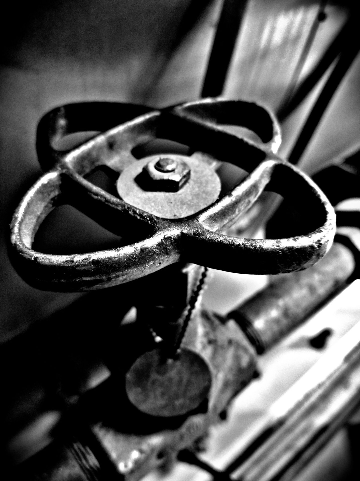
FIGURE 1: An old gate valve.
Image courtesy of CMS Controls
This fluctuation in control showed up in the entering and leaving temperature, delta T, across the coil. To achieve the design conditions leaving the coil, we must achieve the design delta T. Control valve selection plays a big part in whether or not we hit the mark. We work for a company that maintains equipment, and we’re not neglecting the impact a dirty coil or poor airflow can have on the delta T, but we want to focus on the control valve. It’s a small piece of the system and it plays a big part in the efficiency.
The two-way valve will throttle or open based on the deviation of the leaving temperature from the set point.
Valves have various responses to flow when they are opened or closed. They could be linear in response, meaning that for every 10% movement in the valve position, flow changes by 10%. It seems like a perfect valve, and we should be able to control based on this, right? Until it’s installed on the coil and the response of the valve and coil together looks like a quick opening valve, and the leaving air temperature seesaws up and down. In this case, an equal percentage valve applied to the coil gives a linear response, and the leaving air temperature is maintained at the set point.
A couple of typical valve types we select are ball valves and globe valves. These valves, when selected properly, offer good control but not great control. They are sized based on a given flow rate at a specified differential pressure, yet the system pressure is constantly changing. The equation for flow through a valve looks like the following:
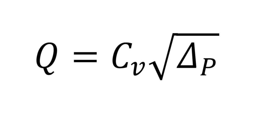
Q = Flow in gpm
Cv = Valve flow coefficient
ΔP = Pressure drop across the valve
A change in the upstream pressure will impact the flow through the valve and coil. An example of this is the change in flow while taking a shower and someone flushes a toilet. It may not be quite as dramatic as that, but you get the picture.
If the sun would remain in one spot and the building occupants never moved around the building, the solution would be simple. System water pressure changes affect the flow through the valves and the leaving air temperature controls suffer as a result. Fortunately, there is a third type of valve called the pressure independent control (PIC) valve, which will keep the flow to the coil constant regardless of what happens in the rest of the hydronic system.
The PIC valve, which is a type of two-way valve, has three parts. First, it has a regular valve to open and close. Second, it has a pressure regulator, which acts as a buffer against hydronic system pressure changes. Third, it has a flow-limiting component that sets the maximum flow through the valve. Combined, these parts each participate in maintaining the required flow through the coil to achieve a more stable leaving air temperature and delta T on the hydronic system. Why does delta T on the hydronic system matter? Anytime there is an unpredictable performance in the system, a situation arises where the system has to find a new equilibrium. Having a constant delta T across the supply and return of the central plant makes it easier to stage equipment on and off.
A variable primary hydronic system with PIC valves is an efficient and controllable design to move water through a building. The downside to this design is the added cost associated with using VSDs and PIC valves. The VSDs will not only improve the efficiency of the system but also extend the life of a pump motor with its soft start feature. The PIC valves increase the speed of selection and commissioning of the system as they are preset to a maximum flow when fully open, regardless of the system pressure.
Mike Davis, P.E.
Mike Davis has been working in the built environment since 1998. He started as a sales engineer working for York International, selling large chillers, standard modular, and custom air handlers with a strong focus on supporting design engineers. Eventually, he went to work for one of these engineers, Moseley Architects, designing HVAC systems for various clients. He took an energy engineering role with Piedmont Service Group in Raleigh, North Carolina. Here, he supported clients with energy efficiency through optimizing their building automation systems or HVAC equipment replacements. During this time, he earned his certification as a professional engineer in the state of North Carolina for mechanical engineering. He also earned his Certified Energy Manager (CEM) and Certified Measurement and Verification Professional from the Association of Energy Engineers (AEE). He currently works for CMS Controls, a provider for building automation projects in the Georgia, South Carolina, North Carolina, Virginia, and the Pittsburgh areas.

James Regan
James Regan has been working in the building automation industry since 2013. He started as a controls technician for Johnson Controls, working primarily in critical hospital environments. He moved on to an energy engineering role optimizing the automation systems of hospitals with a major focus on maintaining proper air quality settings as efficiently as possible. In 2018, he accepted a role as building systems analyst with Piedmont Service Group. In this role, he supported efforts to increase efficiency through identifying poor sequences, faulty field devices, or failing mechanical equipment. He currently is the analytics manager overseeing the building analytics platform where he supports Piedmont Service Group and CMS Controls with optimizing or continuous commissioning through analytics.