
SCROLL
COMMISSIONING
Commissioning Lead/Lag Pumping Operations: Part III, Functional Testing and Optimization
Lead/lag pumping operations are common control sequences that are littered with nuances that oftentimes prevent them from being properly implemented.
Part I of this series introduced the lead/lag control strategy as it applies to parallel pump operation and discussed the need for identifying the designer’s intent for a particular system. Part II discussed aspects of the control sequence a commissioning provider should pay attention to during reviews of such sequences. This article will discuss considerations for the functional testing and optimization of lead/lag pumping operations.
The sequence of operation analyzed during Part II has again been made available (see sidebar, “Example lead/lag sequence of operation”) and will be referenced throughout this article.
Example lead/lag sequence of operation:
1. Secondary chilled water pumps operation
a. Lead pump enable/disable
i. Lead secondary chilled water pump will be enabled anytime the chilled water (CHW) system is enabled and will remain enabled for 30 minutes after the CHW system is disabled.
b. Pump speed control
i. Lead pump’s speed will be modulated to maintain system differential pressure at CHW dP Setpoint (initially 8 psid, adj.).
c. Lag pump operation
i. Lag pump will enable when lead pump speed signal increases above Lag Pump Stage On Setpoint (initially 95%, adj.) for Lag Pump Stage On Delay (initially 5 minutes, adj.).
ii. When enabled, lag pump will modulate off same speed signal as lead pump.
iii. Lag chilled water pump will disable when pump speed signal falls below Lag Pump Stage Off Setpoint (initially 60%, adj.) for Lag Pump Stage Off Delay (initially 5 minutes, adj.).
iv. Lag Pump Stage Off Setpoint will not be allowed to be adjusted higher than 20% below the Lag Pump Stage On Setpoint.
d. Pump failure response
i. If lead pump is enabled but status is not proved for 30 seconds
1. Lag pump enables
2. Lead pump remains enabled
3. Non-latching pump failure alarm is generated for lead pump
ii. If lag pump is enabled but status is not proved for 30 seconds
1. Lead pump remains enabled
2. Lag pump remains enabled
3. Non-latching pump failure alarm is generated for lag pump
e. Lead pump designation rotation
i. Lead pump designation will be rotated via a user adjustable schedule, initially set to rotate the 4th Tuesday of each month at 9 am.
ii. During rotation, outgoing lead pump remains enabled for 1 minute after incoming lead pump is enabled. During this period, they will receive the same speed signal.
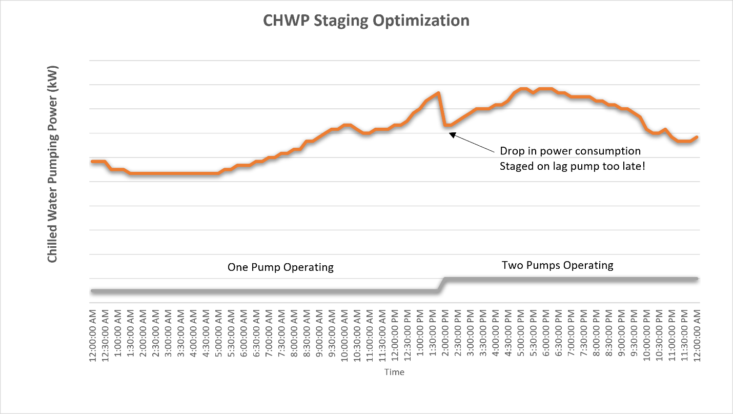
Figure 1: Utilizing a multipoint trend to optimize Lag pump stage on set point.
Image courtesy of Questions & Solutions Engineering
Test Prep
Generally speaking, a functional performance test procedure should be written to test all aspects of the sequence. This test procedure should be provided to the temperature controls contractor several weeks in advance of testing to allow for them to pre-test the system.
Prior to on-site functional performance testing with a temperature controls contractor, it is recommended to review trended performance of the system for at least a week’s duration, preferably including one scheduled rotation of the lead pump designation. This will allow the commissioning provider to better gauge system readiness as well as alert the construction team to any anomalies, so they can be addressed prior to any on-site testing.
Functional Performance Testing
Here are several items to keep in mind during testing.
The fixed differential pressure set point
- Para 1.b. discusses a fixed CHW dP Set Point. Be sure to confirm the value used matches what the testing, adjusting, and balancing (TAB) process determined to be appropriate. Ideally, TAB is complete and the final report is submitted prior to functional testing of the system. In reality, this often is not the case, especially in phased projects and where project schedules are compressed at the end of the project. In such situations, open an issue in the commissioning issues log to ensure the TAB-determined value is entered prior to the system being turned over to the owner.
- There are several approaches that can be used to improve the chances the appropriate TAB-determined value will be retained for sustained operations.
- Ensure the set point is configured to default to the TAB-determined value after a power cycle of the controller.
- Include text on the graphic screen next to the adjustable set point, indicating the appropriate value.
- Configure this set point to be “overridable” instead of “adjustable." This will still allow the flexibility for the operator to make adjustments but will flag the system when the set point value deviates from what has been determined to be appropriate. Note that not every BAS allows for such distinction between overridable and adjustable set points.
- The set point (CHW dP Set point) should be labeled on the graphic with the same nomenclature used in the sequence of operation. This best practice applies to all set points. It makes it easier to verify compliance with the approved sequence and allows for the building operator’s interface with the BAS to be more intuitive.
Lag pump staging
- Paragraph 1.c. discusses staging logic for the lag pump. Typically, the logic should be tested by adjustments to the various set points in lieu of overrides to the differential pressure input reading or manipulation to downstream valves to drive up or down the system flow. This approach will verify set points shown on the graphic are correctly mapped to the set points used in the programming logic. On-site testing should focus on verifying the logic is thoroughly tested. Optimization of the staging set points is typically reserved for a later trend review, as discussed below.
Paragraph 1.c.ii. is intended to ensure both operating pumps operate at the same speed. Several issues can prevent this from happening.
- Ensure communication between the building automation system (BAS) and the variable frequency drive (VFD) serving each pump is consistent. Both VFDs need to be configured with the same input range and reference frequency parameters. For example, a 60% speed signal sent to each pump should result in the same displayed frequency in Hz on both VFD’s display panels. Additionally, the minimum speed on each VFD needs to match, so that one VFD does not bottom out before the other when the control signal decreases.
The programming needs to have a single control loop whose output is sent to both pumps’ VFDs as the control signal, not two identical control loops. Additionally, the same control loop should be utilized regardless of the number of pumps in operation. This can be confirmed by diligently watching the control signal on the BAS graphic as the system stages from one to two pumps.
- On a recent project, trend review prior to testing showed instability at times when the lag pump first enabled. The controls contractor was unable to diagnose the root cause prior to testing. During on-site testing, it was observed that when the lag pump was enabled, the control signal would immediately drop significantly, well below the Lag Pump Stage Off Set Point. The Lag Pump Stage Off Delay discussed in paragraph 1.c.iii was not included in the approved sequence, thus this sudden drop in control signal would immediately disable the lag pump, creating instability with the lag pump repeatedly enabling and disabling. The root cause was that two identical control loops (one for single pump operation, and one for parallel pump operation) were programmed, but, for whatever reason, their outputs did not match. The second control loop was removed, and the first was instead used for control in all instances, regardless of the number of active pumps. This immediately eliminated the instability previously seen.
- Paragraph 1.c.iv is a safety net to prevent someone from unknowingly making set point adjustments that would promote instability. Attempt to raise the Lag Pump Stage Off Set Point above the Lag Pump Stage On Set Point, and vice versa. This is a provision in the programming that is often skipped.
Optimizing Set Points
For any given system, there will be a range of flow rates that could be stably maintained by operating either one or two pumps. There will be point where it is more energy efficient to operate two pumps instead of one. An optimized Lag Pump Stage On Set Point should be at that time. What that value is will vary between different systems. However, often there is enough data available for the building to inform engineers what that optimized value is. For example, if pump power consumption is an available point on the BAS, set up a multiple point trend that displays both the number of operational pumps as well as the collective power consumption (see Figure 1). A trend review, once the system is fully operational, can identify if collective pump power consumption is reduced or increased when the lag pump is staged on. An observed reduction in power consumed would indicate the Lag Pump Stage On Set Point being utilized was too high, thus the lag pump was essentially being staged on too late. An observed increase in power consumption would indicate too low of a value, thus the lag pump is being prematurely enabled. Iterations of this trend analysis, followed by minor adjustments to the Lag Pump Stage On Set Point, will quickly zero in on the optimized set point value that results in negligible changes in pump power consumption.
If the Lag Pump Stage On Set Point is optimized for energy savings, then the Lag Pump Stage Off Set Point should be optimized for stability. The control signal will naturally begin to drop when the lag pump is enabled. You do not want the difference between the set points to be so small as to promote cycling of the lag pump. Conversely, you do not want the Lag Pump Stage Off Set Point to be a value so low that the control signal never drops low enough to stage off the lag pump. ASHRAE Guideline 361 refers to this as the system getting “stuck” in parallel pump operation. Such a scenario is common when the Lag Pump Stage Off Set Point is hardcoded, as it seems the default value of choice for both designers and controls technicians is 40%, which is often too low. Review the trends after the system if fully operational to see how much the control signal initially drops when the lag pump enables. For example, if it was reduced by 18 percentage points, then maybe the Lag Pump Stage Off Set Point should be made 22 percentage points lower than the Lag Pump Stage On Set Point.
It may not be possible for the commissioning provider to perform such post-testing optimization in every project. If not, provide instructions to the building operator to allow for him or her to carry out such tasks.
Conclusion
This concludes a three-part series of commissioning lead/lag pumping operations. It’s a common control sequence that is littered with nuances, preventing it from being properly implemented.
Reference
1ASHRAE Guideline 36-2021, High-Performance Sequences of Operation for HVAC Systems.
Miles Ryan, P.E.
Miles Ryan is a commissioning engineer at Questions & Solutions Engineering. As a major in the Air Force Reserves, he serves as a mechanical systems instructor at the Air Force Institute of Technology. Contact him at miles.ryan@qseng.com.