Feature

SCROLL
Smoke Control — Designed for Failure, Part 3
Examining typical design shortcuts that may well amount to failure.
This article will explore some real-world smoke control applications with a focus on using National Fire Protection Association (NFPA) 92 as a resource for the design and implementation of a smoke control system. This information will pick up on my last article, “Smoke Control – Designed for Failure,” and will be done with an eye toward looking beyond some typical design shortcuts that may well amount to failure. These issues are all easily avoided by eliminating wishful thinking and specifying the requirement clearly in the smoke control rational analysis report. For special inspectors, these are issues that fall through the cracks far too often.
Designers can easily be caught up in the calculations: design fires, air pressure and flow calculations, and more from NFPA 92. The NFPA standard covers so much more, and the best calculations won’t matter if implementation falls short.
Keep in mind, throughout the U.S., designers and installers of smoke control systems are working under several layers of regulatory criteria, including the building and mechanical codes, which are likely based on the most recent edition of the International Code Council (ICC) available in the U.S. at this point in time.
NFPA 90A also applies. This article will demonstrate when the most stringent criteria occurs and how to proceed accordingly. For the most part, these sources of criteria are fairly consistent.
Sometimes, the simplest systems, such as stairwell pressurization or even subduct exhaust, can fall prey to wishful thinking. In others, it’s the more complex multi-zone systems in select occupancies that really do need more attention.
Wishful Thinking Case No. 1
Myth: The weekly self-test requirement from the building code (IMC 513.12.1, NFPA 92 6.4.8.6) isn’t really important enough to disturb normal building operations.
The weekly self-testing program is commonly missing at the commencement of commissioning, or, if it’s done, it’s quickly undone shortly after commissioning. Usually, this situation is discovered later when returning for either tenant fit-outs, renovations, or semiannual/annual periodic testing.
Equally unfortunate, the first stop on-site to the printer at the Firefighter’s Smoke Control Station (FSCS) too often reveals a repetitive series of faults for the same device(s) reporting week after week. So, the self-test may indeed be running weekly, but nobody is paying attention or doing anything about the reported faults until periodic testing occurs.
There’s actually quite a bit to unpack here. Most of the smoke control system’s end points are unable to be checked for proper functionality except when activated and not in the quiescent state. Only the control circuit is continuously supervised up to the point of interface or at least it should be. Wiring faults, or circuit supervision, won’t report a control damper that is malfunctioning. The weekly self-test accomplishes this.
This reinforces the importance of the weekly self-test. The individual components of the smoke control system need to be exercised to put them in a state where they can report a problem. Then, the weekly test record actually needs to be checked to recognize any problems, so as to be able to take appropriate corrective action in as timely a fashion as is appropriate for a life safety system, i.e., do not wait until the next semiannual/annual test.
For multi-mode smoke control systems, running every possible sequence would take hours and significantly interfere with normal building operations. These are legitimate challenges, and giving short shrift to the effort is the likely source of problems surrounding poor implementation of weekly self-tests, because that isn’t the purpose of weekly self-tests.
Sequencing changes don’t just magically appear but rather are tied to programming and infrastructure changes. These changes are validated whenever the renovation or revision activity occurs. This isn’t the point of the weekly self-test. Any change requires an appropriate level of recommissioning at the time the change is made (NFPA 92, 8.7.1).
The weekly self-test requirement doesn’t negate this need nor is it intended to. Instead, each component is intended to activate in a safe sequence, and during that exercise, each component confirms it is individually still capable of functioning. Elegantly done, in most cases, this should not interfere with normal HVAC operations, which is exactly why we need to take care to define exactly what we expect from the weekly self-test and stipulate the limits on allowable adverse impact to normal operations. Do it upfront and early in the process. And although it may seem intuitive, this is also why we need to take care to validate proper implementation of the weekly self-test as part of system commissioning. Directly approaching the issue during training/operation and maintenance documentation is also necessary to avoid predictable shortfalls in this important life cycle activity once taken by facility management.
In extreme cases, a careful self-testing program cannot avoid unacceptable interference with normal building operations. In these cases, the agreed upon individual system components may be bypassed during weekly self-testing. Agreed upon means with the authority having jurisdiction (AHJ), in writing. The designation of a select list of components isn’t a ‘get out of jail free’ situation. Alternative arrangements for these components, including supervision of the power to the affected devices, downstream of all disconnects, along with additional periodic testing (IBC 909.12.1, NFPA 92 6.4.8.7), must be provided.
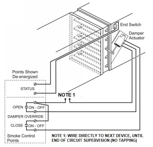
FIGURE 1: Proper power supervision.
Images courtesy of Conquest Firespray
Take care to verify power to multiple dampers on the same breaker/circuit. It is not sufficient to verify the breaker position or even power at the last device necessarily, if power to devices is t-tapped along the circuit, i.e., not looped back to the trunk path akin to an NFPA 72 IDC circuit routing method. Standard power wiring practices would not be suitable here. Monitoring power only at the last device on the power circuit can be accomplished though. Checking correct means and methods during commissioning is essential. Expect to do some j-box investigation and open circuit testing for validation of proper single point monitoring on the circuit.
Be sure to have any approved self-test alternatives and the list of included devices as part of the special inspection report available at the FSCS for the life of the system. This process is best served from the outset by overt inclusion of self-testing performance expectations in the rational analysis.
Wishful Thinking Case No. 2
Myth: When in doubt, choose a combination fire/smoke damper. It’s better to provide more than less, just in case.
On the surface, this oversimplification makes sense. It takes less time to analyze the building compartmentation against the purpose of the ductwork. And, if one believes more is always better, then he or she may believe they’re acting in best-practice territory.
Fire dampers are permitted in smoke control systems when they will not interfere with their functionality. Please focus on that last part. Keep this top of mind.
Unfortunately, in practice, fire dampers are deployed with the belief that more is better, which is not only counter-productive but outright prohibited (IBC 717.2.1) for active smoke control situations.
The exercise to evaluate and eliminate fire dampers that will interfere with any active smoke control system is important. Nonetheless, the necessary smoke dampers must be provided, even when the fire damper is omitted necessarily. This is when the “more is better” logic can creep into design to failure. Let’s cover some of these situations and apply the correct alternative protection. The kind of air service can address the omission of smoke dampers, but it cannot address the omission of fire dampers. Keeping smoke at bay is different than keeping the duct stability and integrity intact so as to be able to do so without adversely affecting compartmentation.
Smoke control systems ductwork is categorized into two kinds of air service: Those that are expected to move products of combustion (smoke exhaust) and those that are expected to move supply air (makeup, airflow, or pressurization). This damper discussion is not limited to just the smoke exhaust ductwork. Remember, hot layer temperatures at typical ceiling heights (sprinkler controlled or not) will exceed the threshold temperature for most listed fire dampers or combination fire/smoke dampers. Shorting a proper analysis by defaulting to high-temperature fire dampers isn’t the solution either. Fire dampers listed to ANSI/UL 555, “Standard for Safety Fire Dampers,” have a maximum link temperature of 286°F but are available as low as almost half that limit (Reference NFPA 90A, Section 5.4.5.2.2.1).
The available fire damper temperature range is similar to that for fire sprinklers. Differently, though, sprinklers are activated in environments that are usually easily assessed as being subject to direct exposure to the fire effects.
For a smoke exhaust duct, a similarly direct internal exposure may indeed be happening as air is drawn by design into the duct. Dilution effects could reduce these temperatures before the smoke reaches the nearest fire damper though (NFPA 92 4.2.3.2). Regardless, if you aren’t doing dilution calculations, then such assumptions are indeed wishful thinking.
For a supply air duct, direct effects inside the duct would be limited perhaps to the typical delay between initiation and activation of the fan by the detection and control systems (NFPA 92 4.5.3). That short period can readily be enough if minimum Sheet Metal and Air Conditioning Contractors’ National Association (SMACNA) duct fabrication and supports are your design. In either supply or exhaust ductwork, the interior unexposed temperature for ductwork is expected to reach somewhere in the range of ~400°F according to the applicable test standards, even for insulated fire-rated duct systems.
There is no guarantee or even expectation that fire damper temperature thresholds are inherently avoided due to a duct’s kind of air service. There are other scenarios, but let’s leave these few as actually being of sufficient concern, because, for this discussion, they are.
These are not esoteric considerations. There are many real-world fire scenarios that are probably going to render the smoke control system inoperable if fire dampers are placed in the ductwork. This is the reason for the applicable regulatory criteria around fire dampers (IBC 717.2.1). It’s not just bad practice or even optional for that matter. This language prohibits fire dampers, and these are the legitimate reasons why it is so.
You must still provide any necessary smoke dampers. But, consider what ‘necessary’ means in this context. Smoke dampers along passive partitions and barriers must also be omitted where they would interfere with active smoke control methods (IBC 717.5, multiple exceptions apply). Again, more is not better. Take the care to examine and eliminate any smoke dampers that are not essential to any active smoke control system. This exercise is necessary.
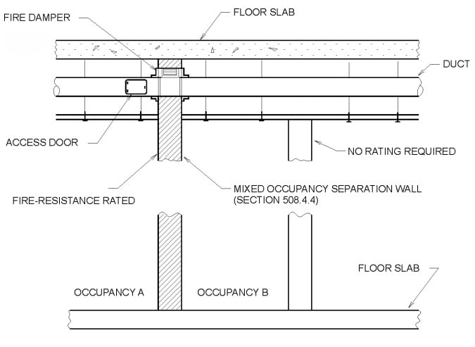
FIGURE 2: An example of a fire damper that is normally required in a rated wall.
Recognize that if a smoke damper is ultimately deemed necessary, a designer must avoid the temptation to provide combination fire/smoke dampers in those locations under the “more is better” philosophy. The fire damper functionality of the combination damper may still be a problem for all the aforementioned reasons. After all, with a little examination, to the degree it matters in this regard, they are still fire dampers.
Even combination fire/smoke dampers, which are designated as remotely resettable, cannot safely be relied upon in this regard. Careful inspection of product data will reveal an upset temperature at which the remote reset capability is over-ridden locally. When this happens, just like any other fire damper, operation cannot be achieved from the FSCS. In these cases, the damper characteristics remain susceptible to interruption of the smoke control system’s functionality.
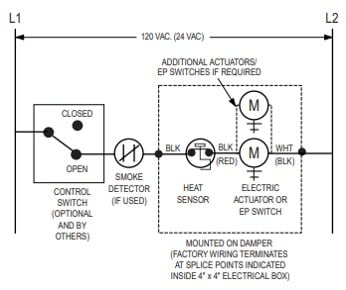
FIGURE 3: A combination damper local temperature sensor defeats the firefighter’s smoke control station (FSCS) override.
Sometimes, designers are certain they’re fully within their purview to provide dampers. For example, some language appears to direct provision of fire dampers at shaft connections for horizontal offsets (IBC 717.1.1). The shaft is protected. Compartmentation is intact. Duty done? This section is inherently incompatible when it comes to life safety air services. Pursuit of more economical SMACNA ductwork that can safely fall away during a fire isn’t going to serve a smoke control system exactly when they’re needed. In-line dampers would indeed protect the shaft, but they will also interrupt the associated air service. That may be fine for general environmental air service, but a designer can’t do that for life safety air services.
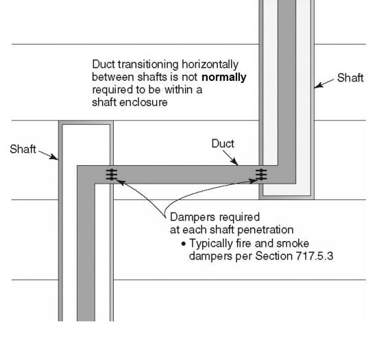
FIGURE 4: A normal horizontal shaft offset.
Even the subduct exhaust system is at issue here. Subduct exhaust systems omit fire dampers as options rather than mandates. But, in so doing, these systems have a very specific means of required alternative protection — in particular they need continuous upward airflow during a fire. Thus, it’s easy to see how continuous upward airflow would be interrupted by any in-line dampers.
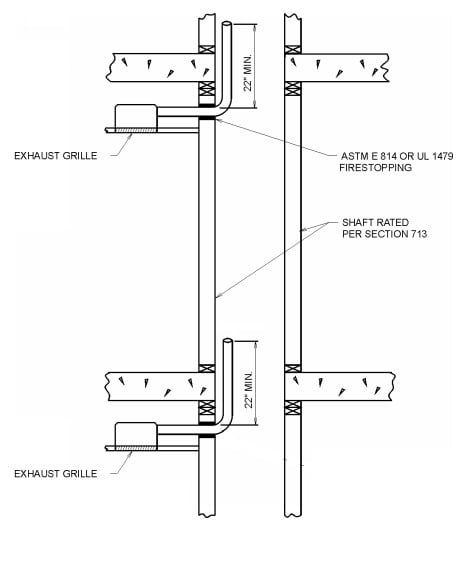
FIGURE 5: A continuous upward airflow used as alternative protection.
Generally, smoke control systems are not required to apply the same rather specific means of alternative protection that subduct exhaust systems do. But, make no mistake, when directed to omit fire dampers as a mandate, some alternative protection must be provided.
Alternative protection means providing the same protection for the penetrated wall or floor assembly as the damper would have. What protection would have been afforded by omitting the fire damper?
Fire dampers are universal in their protection for fire penetration. They close for a fire inside the duct, for a fire outside the duct, and without regard for which side of the damper the heat originates. So, there’s your litmus for alternative protection. Fire-rated ductwork is the most economical solution to omitting these fire dampers. Be specific when specifying this solution; however, because when left ambiguous, this solution can lead to unexpected failures.
Wishful Thinking Case No. 3
Myth: I don’t need fire-rated duct for smoke control ductwork when I omit dampers, because I heard there was a 20-year-old report on steel SMACNA duct that says so. Besides, smoke control systems only need to operate for a short period.
There are indeed research reports on this subject, but these tests were fire engulfment tests completed toward conformance with IBC 717.5.2 Exc. No. 1, where the penetration simply didn’t cause wall or floor failure under a single, rather-specific fire scenario. What matters under the alternative protection litmus is whether the penetrating duct did or did not have openings; otherwise, we’re looking at an incomplete justification.
This kind of limited testing does not address the internal exposures that also must be considered. The kind of air service is irrelevant, which we will find from several codes, standards, and other sources, upon further examination.
Remember, alternative protection must provide the same performance the fire damper would have for all probable fire scenarios, not just engulfment scenarios without duct openings. Besides, the test specimens were anything but minimum SMACNA construction and the document can’t be referenced if it wasn’t fully read and understood.
So, if a design isn’t completed for fire-duct-grade steel fabrication, the associated installation wouldn’t be close to offering even the limited performance achieved during these engulfment tests. This overly simplistic rationale is applied more often than one would hope, particularly when it comes to systems designated for two-hour performance commensurate with the protected shaft rating, e.g., stairwell (IBC 909.20.6.1) and elevator shaft pressurization systems (IBC 909.21.3).
How about other smoke control systems? Defend in-place or selective evacuation occupancies could expose ductwork longer than necessary for general alarm situations, because these are multi-mode smoke control systems whose common infrastructure is not exempted from this analysis (NFPA 92 4.8.1 and 6.4.4.1.3). Consider a series of relocations or evacuations, accumulating the greater of 20 minutes or 1.5 times a timed egress (NFPA 92 4.5.1.2 and 4.5.4). Is any other non-dedicated or dedicated smoke control ductwork at risk (NFPA 92 4.9 and 6.6.2)?
Evaluation service reports (ESR) from International Accreditation Service (IAS)-certified test labs or other approved agencies are readily available these days, and you’ll find they directly address this concept. In all cases, you will find direction for achieving alternative protection whenever a fire damper is omitted. For a ductwork penetrating a two hour or greater fire barrier, the answer is Duct B/Conditions C & D. Otherwise, only limited exemptions exist for penetrations of one-hour barriers and partitions, and ductwork will still need to be checked for conformance.

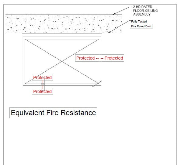
FIGURE 6 & 7: Proper and improper applications of fire-rated duct used as alternative protection.
The first article in this series states that just because there are no openings in certain compartments along the duct route, this does not relieve the full protection intended by fire inside and fire outside capability. It may be intuitive that exhaust ducts have products of combustion inside. Reading the test specimen descriptions from the International Organization of Standardization (ISO) and ASTM test standards can falsely lead to assessing the fire inside test specimens as field conditions. In this case, a designer landed in the right place, but it was by accident, because this logic would just as well lead to applying Duct A/Conditions A & B when omitting fire dampers at supply air duct penetrations. This concept around alternative protection is not supported by any adjacent compartment fire scenario for the exact same stretch of ductwork. This is the reason Duct B/Conditions C & D must be used, and the reasoning is actually quite simple. Any scenarios based on air service that appear to qualify for one-sided testing actually have counter fire scenarios (one or more adjacent compartment fire scenarios), where there indeed are duct openings.
Every duct system not wholly contained within a single compartment has some unprotected opening existing between compartments — even stairwell and elevator shaft pressurization systems do this. We don’t get to cherry pick fire origin scenarios any more than default to minimum SMACNA criteria without a healthy serving of wishful thinking (NFPA 92 6.6).
How far into a zero-hour fire-rated duct (Duct A) must interior fire effects extend before risking failure? This question actually isn’t supported by any of these codes and standards used in this analysis. But, some of the basic myth-busters can be covered here. To start with, reduced cross sections won’t meet design airflow rates. Will the system still work? One joint or support failure is all it takes to compromise the duct system. It’s just like pushing the first domino. Will the resulting failure compromise an adjacent compartment? Even if a zoned smoke control system by analysis needs only 20 minutes of functionality to meet egress requirements, does the risk to passive compartmentation matter after that? Smoke barriers aren’t rated for 20 minutes. Don’t start confusing the egress time with the minimum fire-resistance requirements.
Further, consider that average hot layer temperatures may not be the only fire scenario that should be considered. One can’t assume the fire plume and ceiling jet will always be ‘over there’ somewhere away from the duct or openings in the duct. Direct fire effects will significantly exceed the average hot layer temperature.
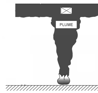
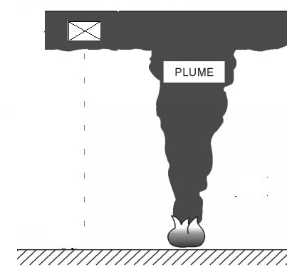
FIGURES 8 & 9: Fire plume and ceiling jet effects versus the average hot layer.
Why would this matter for supply air/pressurization ducts anyway?
Contrary to conventional wisdom, even stair pressurization systems may be selectively programmed (NFPA 92 6.4.6.1.2), so they may not always be pressurized;
Multi-mode smoke control systems don’t have the capacity or sequencing to always pressurize every supply air duct (NFPA 92 6.4.4.1.2), so they won’t necessarily follow fire spread across multiple zones automatically;
Ductwork may pass through the zone of fire origin on its way to an adjacent compartment that needs to be pressurized (NFPA 92 6.6), so adjacent compartment fire scenarios are very real;
Direct fire effects may be at or near enough to a duct opening before air is supplied (e.g. NFPA 92 5.5.4), so cross section deformation, joint, or support failure of a duct are legitimate concerns; and
FSCS operators may actually need to exercise their ability to change an automatic sequence (NFPA 92 6.4.5).
Upon reading NFPA 92, if a robust rational analysis is performed, and if designers don’t rationalize their way toward a design failure, these are all minimally required functionalities for the smoke control system. ICC’s Acceptance Criteria AC179 says a fire damper may be omitted when there are no openings within 6 feet of the penetration and fire-rated ducts, tested to both fire inside and fire outside, are applied. Air service, supply versus exhaust, is irrelevant in this regard.
NFPA 92 (4.2.3 and 6.6.3) requires all smoke control system infrastructure be suitable for probable fire exposures. If there’s any doubt what this means, NFPA 90A, as referenced by NFPA 92 6.6.1, makes clear those scenarios are to include fire exposures from both inside and outside for anything serving as both duct and shaft — regardless if the system is configured by conventional construction enclosing SMACNA ducts or by applying fire-rated ducts instead. NFPA 90A 5.3.4.3 and 5.3.4.4 correlate only to Duct B (ISO)/Conditions C & D (ASTM).
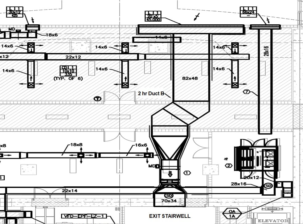
FIGURE 10: Proper use of fire-rated duct as alternative protection for mandatory fire damper omission.
By all code paths, active system contributions, whether sprinkler for smoke control, were already considered in the setting of minimum fire-resistive requirements. So, please don’t double dip with some overly simplified rationalization for using Duct A (ISO)/Conditions A & B (ASTM) on the basis of providing active systems that were already minimally required themselves. This concept directly contradicts the available code and standard references on the subject. And, unless a fire-rated duct design is implemented substandard to associated details for that design, the concept of cost savings in this regard is baseless — it’s an unnecessary risk that won’t withstand scrutiny.
It’s a consummate example of wishful thinking to default to 20-year-old partial tests of super-SMACNA-grade ductwork without penetrations when that level of duct fabrication isn’t in anybody’s basic Construction Specifications Institute (CSI) specifications. Duct openings across compartments are found in all but the case a single system for a single compartment — think atria with direct top exhaust and makeup air to and from the exterior — that’s about it. Even references for duct support state it must provide a “substantial” connection to the structure. Does that sound like basic SMACNA support methods like wire and strap? The idea that minimum SMACNA ductwork fabrication, joining, and hanging methods can serve as even general smoke control infrastructure are baseless. There’s a predictable outcome from this shortcut: Latent risk, at best, all the way on through late-stage delays. Designers don’t want clients facing recognition of the problem during the commissioning process or worse, during a fire event. Once identified, this issue is fairly easy to avoid. Directly call out the need for Duct B (ISO)/Conditions C & D (ASTM) and do it clearly in the rational analysis (IBC 909.4.4). Specificity is the key.
Joseph Hauf, P.E.
Joseph Hauf, P.E., is a licensed professional engineer in multiple states in the mid-Atlantic and Southeast U.S. He made his start in life safety engineering with Rolf Jensen & Associates Inc. out of its Washington office in 1988 while studying in the fire protection engineering program at the University of Maryland. He has more than 30 years of experience in life safety and fire protection engineering for complex, high-rise, and mixed-use projects in various jurisdictions in the U.S. and abroad. His extensive experience with smoke control systems and their associated infrastructure over that time paved the way for development of this insightful article. Contact him at jhauf@conquest-firespray.com.

Lead image courtesy of Pixabay.