

feature
TAB – The ‘A’ is for Adjust
Air does care, as it turns out.
Air does care, as it turns out. I vividly recall the constant volume exhaust system that established my confidence in the proportional balance method. It was vast, sprawling throughout a big complex of a building, catching all the odds and ends that didn’t require their own separate fans. Nearing almost 100 inlets, access to the entire system required an obstacle course of flow hood adapters, ladders, and lifts. I was anxious for what multiple days of labor would provide, given that my fully open path was barely 40% of design. As a new hire at the time, I very much wanted to prove my value as well. While I would see gradual changes as I completed my iterative tasks, I wouldn’t have a sense of whether or not I would “make it” until about 20 hours into the process — applying practice to a theory I had previously only tested in smaller quantities.
We testing, adjusting, and balancing (TAB) technicians inhabit and bridge the gap between theory and practice every day. Our role in tuning building systems requires that we accommodate the small and sometimes significant differences across the planned design and the installed conditions. To even begin our work, we must ensure that all trades before us have completed their tasks. We interact with every unit switch or disconnect, all terminal units, every valve, every damper, and each flow and pressure sensor. While the project teams who hire us do their best, a TAB team’s efforts are often spent on quality assurance and resolving issues as much as the science and art of TAB. As with most construction and renovation, open communication and collaboration lead to the best outcomes1.
Such collaboration is embedded within the most referenced TAB standards and specifications.2,3,4 While the certification programs for technicians performing TAB to these standards have some variation5, a core concept for achieving efficient system performance common to them all is the proportional balance method — though some may think this is only needed for constant volume systems, such as the aforementioned one. As realized by others7, and as I outline in the following, this eloquent and counterintuitive approach also applies to automated, variable systems, and perhaps even some systems comprised of human rather than mechanical elements.
Ratio of Tolerance
Unless specified otherwise, a TAB technician strives to bring air and water flows to within +/-10% of design values. Sometimes, design engineers desire a different range, such as +15%/-5%. Realistically, systems cannot be balanced more closely than 5% due to accuracy of test instruments (+/-3%). The ratio of tolerance is calculated by dividing the upper limit by the lower limit. For example, with the default of +/-10%, the equation is 1.10 ÷ 0.90 = 1.22. When making adjustments, the ratio between the adjusted and fully open (key) flow percentages of design must be compared and tuned to less than this value to be in proportion. When using pressure-independent devices, the technician must determine in what range of accuracy do those operate and under what conditions? Balancing can only verify within the parameters of the installed equipment.
Total Within Range
Along with all the effort to determine thermal loads, design distribution systems, and install them within the confines of structural and architectural aesthetic is the labor to balance them in the final conditions. For the adjustments to be maintained, the total flow of a system must be within 80%-120% of design. Changes of larger magnitude will disrupt any proportioning that has been performed. Early identification of systems outside of this range will give the project team a better opportunity to address and implement any required solutions. For variable systems, this total must be for the anticipated diversity with the design, where not all terminal units will need full flow at the same time.
Fully Open Path
The primary characteristic of any system balanced for efficiency is that each branch has a fully open path between the main or terminal unit to at least one outlet, inlet, or device (such as a hydronic coil). This pathway, often called the “key,” is identified by a survey of the whole system and calculating the percentage of design for each flow. The outlet with the lowest percent of design is the key. TAB technicians must ensure all obstructions have been eliminated or minimized. Questions must be addressed, including: Have all protective films, filters, and strainers been removed; are any flexible connections aligned and free of constriction; and are the dampers fully open?
On the topic of dampers, fire life safety (FLS) dampers of all types — fire, smoke, and combination fire-smoke — must be considered. Even a partially closed or obstructed FLS damper will affect the airflow for all the outlets or inlets of a system. Whether new construction or existing systems, chances are that some FLS dampers require correction6. A frequent symptom of unaddressed FLS damper issues is inadequate access. To ensure continued maintenance of FLS dampers, access doors and panels should be sized and placed so a technician can reach the damper components with two hands at the same time — more than what might be provided when inspection is the only consideration or when the minimum of 12 square inches, as listed in National Fire Protection Association (NFPA) Standard 105.7.3.2 is followed.
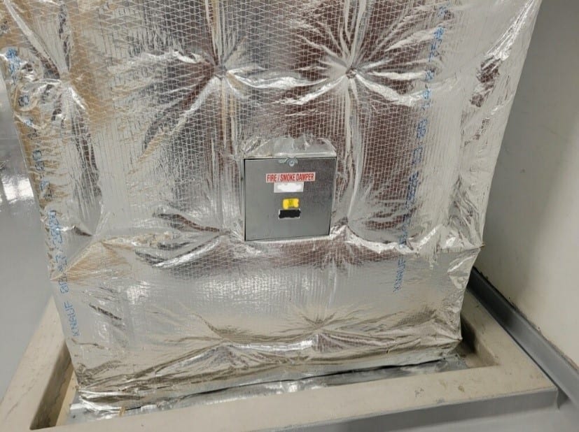
FIGURE 1: This FSD access door meets minimum size requirements but is placed only for inspection, not testing and service.
Photos courtesy of Soph Davenberry
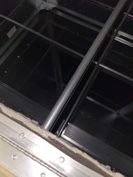
FIGURE 2: Sure, I can probably squeeze through that access door, but I probably shouldn't.
For the large constant-volume exhaust system in my example, even with all obstructions removed, my key inlet was still only around 40% of design. I was going to have to shift a lot of air to bring everything into proportion.
Start Low
Unique to, and perhaps the most counter-intuitive step of, the proportional balance method is that once the initial readings are taken and the key pathway is identified, the next flow to adjust is that of the next lowest percent of design. Going by the numbers, adjustment is only necessary when the ratio of design of the flow being proportioned to the key flow is greater than the ratio of tolerance. For my example system, with the key starting so low (let’s say 42% of design), only an inlet flowing at 52% of design or more would exceed the ratio of tolerance of 1.22 for +/-10% (0.52 / 0.42 = 1.24). For that large sprawling system, a half dozen or so inlets were already in proportion to the key inlet (were flowing less than 52% of design). I left them alone for the time being and proceeded to those inlets at 52% of design and higher.
Adjust Once
The driver for why proportional balance is the preferred method is because, for the most part, a TAB technician will only have to adjust a volume damper or circuit balance valve once in the process. A flow proportioned to the key flow will maintain that proportioning as subsequent adjustments are made to the remainder of the system. For my constant-volume exhaust example, I jumped all over that complex building: near to the key inlet for some adjustments, then perhaps to the opposite side or another floor for the next. That might seem like more distance, but I saved a lot of labor by only having to set up at each location a total of three times: 1) initial (preliminary) readings; 2) proportioning to the key; and 3) final balanced readings. (With wireless technology now available for flow meters, the trips to the key outlet can even be eliminated with constant monitoring as well as climbs up and down between the volume damper and the flow hood.)
For automatic, variable systems, the number of trips for each location can be reduced to just one to verify that minimum pressure differentials are met or that a flow cartridge is indeed delivering the required flow — but only if the TAB technician meticulously notes when system set points are changed in the process. Autoflow devices will provide flow within a specified range to a set value only when the differential pressure (DP) across the device meets the requirements. An effective approach is to start with a low system set point (for duct static pressure or differential pressure for hydronic systems) then note increases to the system set point as autoflow devices with DPs below the minimum are encountered. If the final system set point is significantly higher than when the first autoflow devices were checked, they may need a second trip to ensure the maximum DP has not been exceeded.
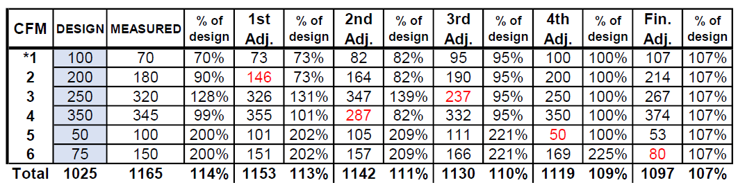
FIGURE 3: The outlets (1-6) are adjusted proportionally — from lowest to highest percent of design (2, 4, 3, 5, 6) — with outlet 1 as the key.
Maximum Effects from Maximum Redistribution
On larger systems, the effects of proportional balance may take some time to be measurable. In my example, constant volume exhaust system, after eight hours and only a third of my way through the system, my key inlet had increased to only 58% of design or so. The first adjustments are small.
As a TAB technician applies restrictions, eventually, much larger quantities are shifted with remarkable results. This is the second half of this labor-saving method — once the process reaches greater volumes, the redistribution follows the prior proportioning so that those outlets, inlets, or devices once starved for flow receive the increases in proportion to the lowest — all moving up together.
What begins with tens of cubic feet per minute (cfm) or liters per second (L/s) can reach hundreds or even thousands of the same in a single adjustment. As I finished my second day on the expansive constant volume exhaust, I was beginning to have faith. My key inlet had crept into the upper 70% of design, and I had some big moves to make the following day.
In Figure 3, the outlets (1-6) are adjusted proportionally — from lowest to highest percent of design (2, 4, 3, 5, 6) — with outlet 1 as the key. Outlets, other than the one being adjusted (in red) and the key, are not typically measured. Values below are merely an example of how airflows gradually change throughout the process with some total flow loss due to increased resistance and leakage.
In the first few hours of my third day, I knew I had “made it.” I was surprised how restricting a couple of the more voluminous inlets didn’t have as great an effect on the key as I anticipated. Yet, overall, I had pushed what felt like a massive bubble, bringing the small differences to fruition as that massive system did indeed proportion out. My final pass was not without some minor tweaks — tiny taps to the damper to allow that last 5 or 10 cfm needed to meet spec. My three days had been well worth the effort to achieve the necessary results.
Building automation systems (BAS) have brought some adaptation for more efficient operation. System set points can be reset based on feedback from terminal devices. The proportional balance method underlies the logic of such systems, scanning system operations with a continual goal of maintaining at least one terminal unit with its restrictive device at least 90% open. For those troublesome devices that are distinct outliers (imagine a trend with most devices at 50% open or less with only one or two driving the system from 90%-95% open) it might be worthwhile to send in a certified TAB technician to look for what stretch of duct or pipe might be improved. One thing’s for certain — regardless of the conditions, we adjust.
References
- “Lessons in Collaboration from Cx Agents,” conference proceedings, ASHRAE 2021 https://www.techstreet.com/standards/seminar-53-lessons-in-collaboration-from-cx-agents?product_id=2238068#product
- AABC National Standards for Total System Balance PDF
- New Testing, Adjusting and Balancing Procedural Standard – Ninth Edition
- TAB Procedural Guide, Sheet Metal and Air Conditioning Contractors’ National Association
- "Testing, Adjusting and Balancing HVAC Systems: An Overview of Certification Agencies,”
Fredrick Meyers and Theresa Pistochini - “Reliability of Fire Dampers, Smoke Dampers and Smoke Control Systems,” James Milke and Robert Ayoub
- “An end to proportional balancing?” Modern Building Services

Soph Davenberry
Soph Davenberry is a field technician for McKinstry and a 26-year member of Sheet Metal, Air, Rail and Transportation Workers (SMART). Find her on LinkedIn at https://www.linkedin.com/in/soph-r-davenberry.
Author photo courtesy of Cadance Sturgeon
[romaset]/[iStock / Getty Images Plus] via Getty Images