
SCROLL
FEATURE
Balancing the Design Flow Rate for Pump Optimization
The ultimate goal of every heating and cooling installation is to provide the desired indoor climate at the lowest possible energy cost.

SCROLL
The ultimate goal of every heating and cooling installation is to provide the desired indoor climate at the lowest possible energy cost. Today’s advanced control technology means that, in theory, achieving this goal is possible. In practice, however, even the most sophisticated controllers don’t always perform as promised. The result is lower levels of comfort at higher energy expenditures. Balancing ensures the plant performs as specified by the designer and operates the way the designer intended. Only through balancing can potential problems be identified and rectified. But, balancing is normally overlooked due to the complexity and investment involved without proper strategy/method to manually balance. Hence, understanding strategic balancing for optimization using balancing strategies, such as the TA Wireless method, with advanced balancing instruments, such as TA Scope — listed in this article by IMI Hydronic Engineering — can make the balancing process easier and more optimal to achieve desired operations and savings.
Balancing prevents overflows in certain circuits from causing underflows in others. It also helps to detect possible oversizing of pumps and verifies the plant provides the functions and performance as intended.
It can help reveal and removes issues ranging from incorrectly implemented balancing calculations to assembly errors, such as incorrectly installed check valves and blocked filters. The balancing procedure allows you to immediately reveal the effects of any disturbances, identify the cause, and take corrective measures. Some common problems we see in unbalanced systems are temperature gradient and instability, inability to achieve installed power, long startup times, high energy consumption, etc. Let’s look at some of these topics in further detail.
Water Flow Rate Distribution in a Variable-Flow System
Underflow occurs frequently in a variable-flow distribution system at high loads. At first glance, there appears to be no reason to balance a system when we have two-way modulating control valves on the terminals to obtain the required flow automatically. However, even after careful calculations, many control valves are oversized based on the available valve coefficient (Cv) from the manufacturers. Fully open control valves cannot be avoided in situations like the startup, large disturbance/change in the load, undersized coils, and when some thermostats are set at minimum or maximum value. In these cases, without a balancing valve, we would overflow some circuits while underflowing or starving the others. Hence, we would notice certain parts of the building being too hot and others too cold.
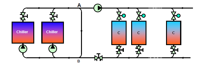
FIGURE 1. An example of a variable-flow distribution system.
Images courtesy of Air Technology Consulting LLC
Using a variable-speed pump will not solve this issue since all the flow changes proportionally when the pump head is modified. Hence, attempting to avoid overflows will simply make underflow more significant. Hydronic balancing ensures that all terminals can receive the required flow and completely eliminate underflows.
System Startup
In distribution systems with variable flow, startup after each setback is a serious consideration, since most control valves drive fully open during this process. This creates overflow, which produces excessive pressure drops in some piping networks, starving the terminals in less-favored parts of the system. The unfavored circuits will not receive adequate flow until the favored spaces reach their thermostat set point, allowing the control valves to be closed. Hence, startup becomes difficult and takes longer than expected. This is costly in terms of energy consumption. A non-uniform startup makes management by a central controller and any form of optimization practically impossible.
In a distribution system with constant flow, underflow and overflow both remain both during and after startup making the problem much more difficult.
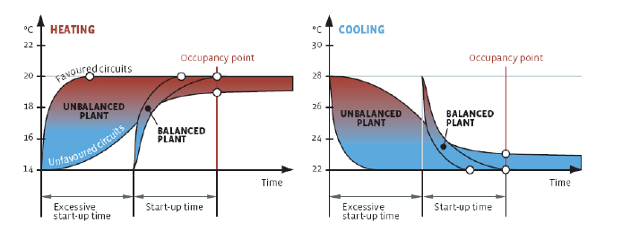
FIGURE 2. An unbalanced plant has to startup earlier, increasing the energy consumption.
Pump Optimization-Strategic Balancing Method
Hydronic balancing provides the opportunity to verify the installation is correctly executed. It enables detection and subsequent correction of most issues, such as air, clogging, etc. Having a proper balancing strategy/procedure, such as the TA Wireless method based on the rule of proportionality, and balancing instruments, like TA Scope, is important for properly balancing a system. It also removes the need to go back and readjust the same valve multiple times to take care of the interactivity that exists in the system.
The strategic balancing method ensures the operation as per design and saves a significant amount of pumping energy. Unique balancing methods can detect the index circuit (the circuit that requires the highest differential pressure) and allocate a pressure drop of 1 foot for the balancing valve on this circuit (minimum pressure drop recommended for reliable flow measurement).
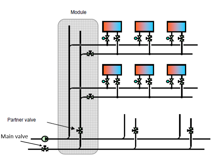
FIGURE 3. A balancing module.
The balancing valves on all the individual circuits/terminals within a branch need to be proportionally balanced. Then, the balancing valves on each branch are proportionally balanced as well. Once the terminals and the branch valves are balanced, the next step would be to proportionally balance the partner valve on each module. Once the partner valves on the modules are set and locked, the final design flow rate is obtained by adjusting the main partner valve for the design flow rate. When this operation is completed, design flow is available at all terminals.
All overpressure is taken and measured in this main balancing valve. Then, the set point of the pump can be reduced with the same value, significantly decreasing the pump’s energy consumption up to 35%. Balancing using proper methods allows performing balancing in phases in new construction independently with each other even using manual balancing products. This also allows flexibility to work on retrofit and expansion projects independently without affecting any existing portion.
Conclusion
Table 1 summarizes the major issues discussed above that exist in the unbalanced plant along with cause as well as false and correct solutions for resolving each issue.
Hence, we can see that hydronic balancing is necessary to ensure the design flow can be reached at every terminal unit to ensure optimal operation of the HVAC system with low energy consumption. Hydronic balancing prevents overflow in some circuits from causing underflow in others, detects the degree of pump sizing, and generally verifies the plant works as intended.
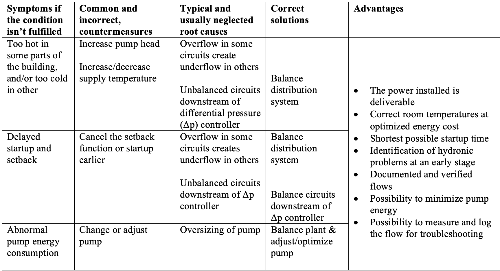
TABLE 1. Major issues (and causes) in the unbalanced plant as well as false and correct solutions for resolving each issue.

Soham Neupane is the hydronic training manager with IMI Hydronic Engineering Inc.

Muslim F. Nazarali is a test and balanae engineer at Air Technology Consulting LLC
[Eoneren]/[E+] via Getty Images