

COVER STORY
Beware of Faulty
Efficiency Claims
If industry outsiders were to add up all the promotional claims related to the energy performance of building systems and their associated energy savings, they could reasonably assume our industry has achieved maximum energy savings and there are no building systems left to improve upon.
In regard to building automation systems (BASs), there is no shortage of various controls solutions, whole building and/or plant optimization packages, and fixes utilizing artificial intelligence (AI) algorithms in this industry. Similarly, there is no shortage of claims of energy savings on behalf of the providers of these solutions. Some of these claims are quite unrealistic, while others are absolute greenwashing. What is the value to the environment when a solution claims a 10% reduction in the source energy use intensity (EUI) if the net source EUI is 200? Is our message to the environment that “it could have been worse,” and the building should still get an award for decreasing the EUI by 20? If industry outsiders were to add up all the promotional claims related to the energy performance of building systems and their associated energy savings, they could reasonably assume our industry has achieved maximum energy savings and there are no building systems left to improve upon. Most new BAS and optimization solutions are far from achieving their promised energy savings.
Further, in order for an industry professional to be able to discern the "noise" from the "real" and valid solutions, one needs to have a good understanding of BAS basics. This article is the first of a two-part series intended to provide industry professionals with a few tools that could help them see beyond the smoke and mirrors.
In general, at the core of each typical BAS controller, there is a library of proportional integral derivative (PID) loops used to control and/or monitor the various control points, aka variables, connected to the controller. Figure 1 shows a sample controls diagram and control logic for a single-duct variable air volume (VAV) box with hot water reheat coil.
A controls sequence loop for the control valve that directs the flow of hot water may be similar to 1) when the space temperature falls below set point, the heating loop shall be enabled; 2) from 0%-100%, the heating loop shall increase the discharge air temperature from the air-handling unit (AHU) supply air temperature to the maximum discharge air temperature set point, and 3) The VAV damper shall be modulated to maintain the measured airflow at the active airflow set point. The active airflow set point shall be the minimum airflow set point. It’s important to note a similar sequence and diagram is presented in ASHRAE Guideline 36, “Advanced Control Sequences for HVAC Systems.”

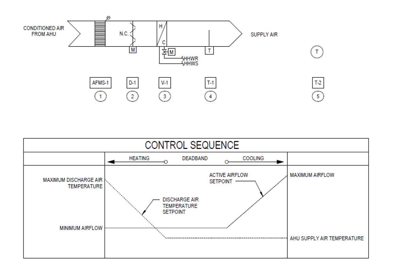
FIGURE 1: A sample control diagram for a VAV box with a reheat coil.
A sample parallel PID loop for the control of the actuator of the control valves that serves the hot water reheat coil is shown in Figure 2.
Any PID controls loop has three components, which could be interpreted as three independent calculations or processes that are executed by a controller before it decides to change the status of a variable, i.e., close or open the valve actuator. These processes are as follows.
- P: Proportional — This process takes a proportion of the current error value, i.e., the difference between the actual discharge air temperature and the discharge air temperature set point. This proportion of the error is defined by the gain value constant, which is typically identified as Kp. Various standard BAS controllers may come with Kp values that are factory preset somewhere between 0.2 and 0.5.
- I: Integral — This process takes all past error values and integrates them over time. This type of computation will most likely cause the integral term to grow until the error is zero. At that time, the integral term will stop growing. If the error reappears, then the integral term tries to eliminate the error by adding in its accumulated error value. The gain value constant for this process is typically identified as Ki.
- D: Derivative — This process/computation is used to estimate the future trend of the error based on its current rate of change. It’s used to “smooth” the operation of the actuator, i.e., prevent it from overshooting its targeted position. The gain value constant for this process is typically identified as Kd.
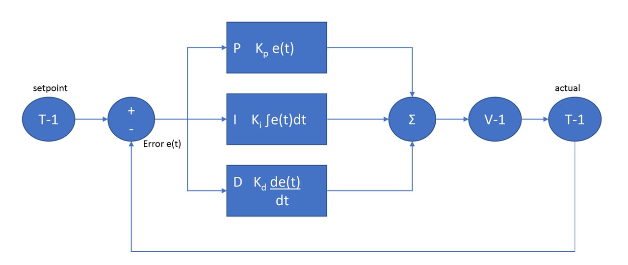
FIGURE 2: A sample PID process for a reheat coil.
It’s important to note there are three types of PID control algorithms: ideal, series (aka analog or classical), and parallel (aka independent). It’s not the intent of this article to describe in detail the science of PID loops, in particular the tunning of PID loops; however, each control loop serves a variable that, in turn, affects a desired outcome, such as maintaining a zone temperature set point, that needs special attention. The gain value constants of a PID control loop for an actuator of a valve that serves an interior office space should be different than the gain value constants of a PID control loop for an actuator of a valve that serves a corner office or a conference room. Far too often, "canned" PID loops released by the controls programmer to control HVAC systems without any modifications to the default settings for the gain value constants are present. In many instances, the Kd constant is set to zero.
Regardless of the type of PID loop used by a controller, only one variable can be controlled to maintain a set point. For example, a sequence that reads similar to modulate the control valve serving the reheat coil to maintain a supply air temperature of 85°F and a room temperature of 72° is destined to fail. One cannot control one variable (i.e., the position of the control valve) to satisfy two simultaneous conditions. It needs to be an either/or approach. This type of situation is no different than using cruise control while driving: One cannot set cruise control at a certain speed and, at the same time, ask or expect the car fuel control system to only use a specific amount of fuel.
So, what do PID loops have to do with AI algorithms? To start, the PID loops are, by definition, reactive. They monitor a set point, and if the set point is not maintained, they react by controlling a variable to try and maintain the set point, i.e., supply air temperature. The PID loop does not know or understand why it is having difficulty maintaining the supply air temperature set point or if the valve actuator is open or not. In regard to the control of an HVAC system, one could see it as being ironic to have a set-it-and-forget-it PID loop used to control a system that is continuously changing and reacting to the environment. The standard BAS PID control loop is a very limited controls approach. Further, should there be a third-party AI solution integrated into a standard BAS, the operation of the controls system, as a whole, may impact the energy efficiency of the HVAC system(s) it controls. Just because one uses AI algorithms to control an HVAC system, it does not necessarily mean the HVAC systems will be more energy efficient. This is because the function (discussed in more detailed below) computed by the AI algorithms is merely an approximation of the mathematical relationships between controls variables; and approximation implies an error in the output of the function. This is where the quality and performance of AI algorithms will play a crucial role in the outcome of the controls process. The flow of information between the cloud and the standard BAS controller is similar to the one shown in Figure 3. Before an engineer allows a third-party AI solution to integrate into a BAS, he or she needs to have a full understanding of the performance of the AI algorithms, in particular a strong understanding of the errors in predictions and the polling time needed by the solution. If the AI solution needs polling every minute, but the BAS was designed to poll no more than every five minutes, then the AI algorithms employed by the solution will most likely not be as valuable as one would expect them to be. This, in turn, will most likely affect the "potential" energy savings claimed by the provider of the AI solution. By the time all of these challenges will come to light, the project may already be built, and an engineer will now have to deal with an owner who is not receiving the energy cost savings he or she expected. The whole process will most likely become a finger-pointing exercise between the engineer, owner, BAS contractor, and provider of the AI solution with the CxA playing a referee role.
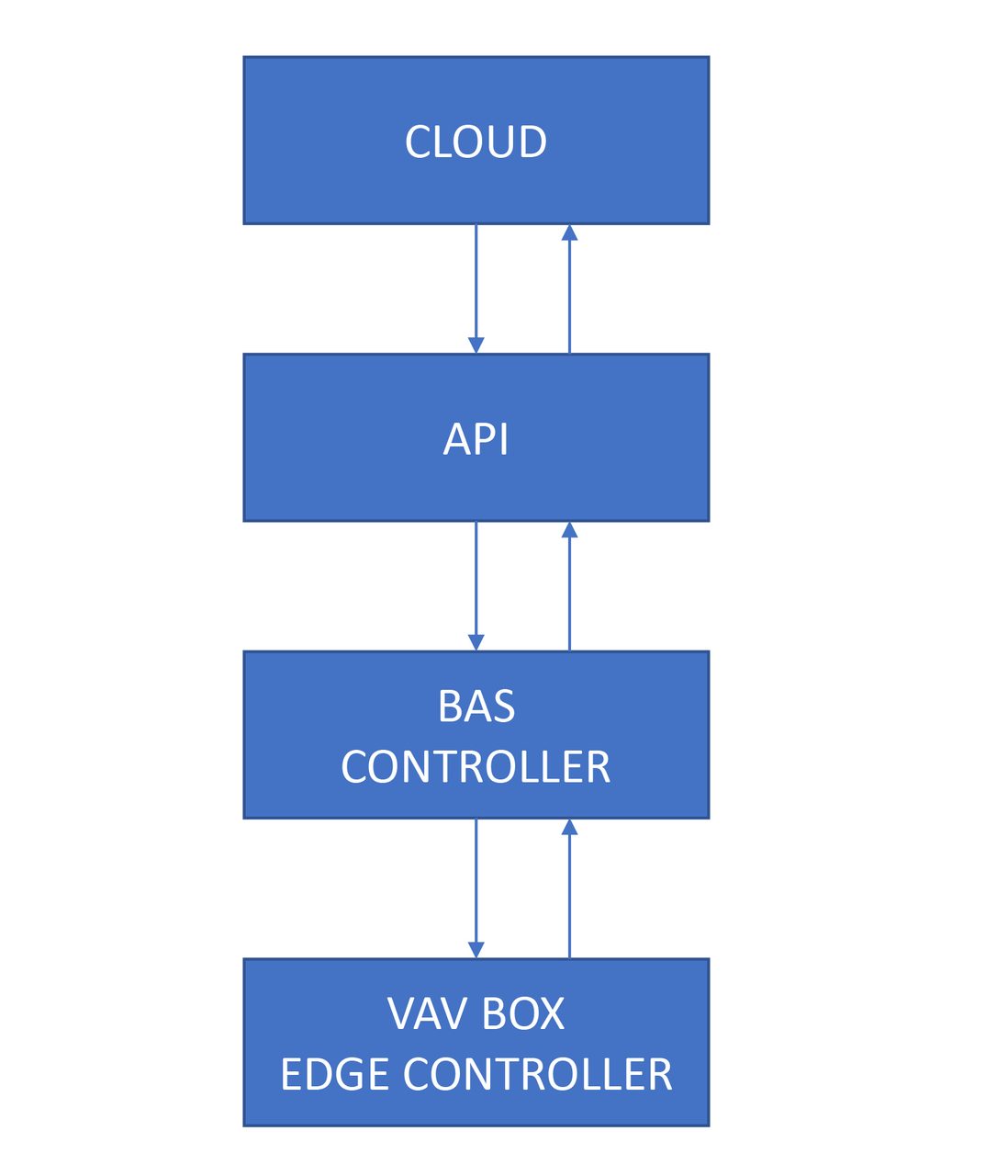
FIGURE 3: A sample flow of information to and from an edge controller.
To try to overcome some of the limitations of PID loops, various controls manufacturers have developed more specialized controllers called edge controllers, with the overall controls system typically identified as edge computing. This type of controller is more advanced than a standard BAS controller, as it has increased computational capacity, can support standard PID loops, and can execute functions computed by AI algorithms. However, the computation of AI algorithms will most likely need to occur in the cloud, because this type of computational process is resource-intensive, and said computational resources are typically not available on-site.
Figure 3 shows a sample flow of information between the cloud and an edge controller. Even though the edge controller can execute AI algorithms, it does not typically have the computational power to (re)train the AI algorithms. A cloud connection is typically required so the AI algorithms can be improved and/or modified to satisfy new operating conditions. In some instances, the edge controller could be connected directly to the cloud without the need to send and receive data through a BAS controller and an application programming interface (API). The API acts as a translator between the cloud processes and the BAS, as it typically converts BACnet information into a "language" the cloud algorithm can understand and process.
What is an AI algorithm? In its most basic form, and as it relates to the controls of HVAC systems, an AI algorithm could be considered as an advanced mathematical model whose output is a function that is called by a controller to provide a value for an output variable based on previously defined input variables. For example, and using the variables in Figure 1, one could attempt to build a mathematical function that has input variables AFMS-1 (the VAV box airflow), D-1 (the position of the VAV box damper), V-1 (the position of the reheat coil control valve), and output variable T-1 (VAV box supply air temperature). As an alternative to manually building such a complex mathematical function, one could use an AI algorithm (i.e., deep learning). In order for the AI algorithm to determine the functional relationship between the input variables and output variable, one needs to first run the VAV box using PID loops. Data will then need to be stored and sent to the cloud. Once enough data has been gathered (i.e., at minimum, a couple of weeks), the AI algorithm can be trained such that it can start approximating the functional relationship between the input variables and output variable. Figure 4 shows a sample controls logic in an edge controller. Once the cloud algorithms have approximated a function, said function is then downloaded onto the edge controller. A PID loop then calls the function every time it needs to change the position of the valve actuator. The main difference between a standard PID loop and this type of edge PID loop is that the edge PID loop is predictive and not reactive; the edge controller is able to predict what the position of the valve actuator needs to be, given the input variables.
Although both options (i.e., a stand-alone PID loop with a cloud AI solution and edge controllers with a cloud AI solution) presented above could improve the energy efficiency of HVAC systems, both approaches are still very limited and limiting. This is because there is a significant amount of human labor required to deploy the program and solutions. It would be very challenging to have a valid estimation of the impact of all prediction errors and all the errors of programming (and not tunning) PID loops. It could easily become a scenario where the overall error/inaccuracy in predictions and operation is greater than the sum total of errors in predictions from the AI solutions.
When is the last time you, as an industry professional, had a brainstorming session (either in the design or construction administration phase) with the programmer of PID loops and discussed tunning strategies that are to be implemented in the chiller water plant controls system? When is the last time you had a brainstorming session with the programmers of the AI solutions and discussed, in great detail, the AI algorithms that are to be used, associated AI algorithm performance metrics (i.e., underfitting, overfitting, root mean square error, etc.), and prediction error mitigation strategies?
Regardless of the option one pursues when designing and deploying a controls solution for a building HVAC system, it is important to note that neither of the solutions described in this article has any capability of understanding what causes an output to be the way it is. Any AI algorithm used to compute the functional relationship between various control variables does not know how or why it arrived at that function, regardless of how small the prediction error. What value does an algorithm bring to a building engineer if said engineer must manually troubleshoot the reason for a chiller tripping on a pressure alarm? Part two of this series, which will appear in the December issue of Engineered Systems, is intended to address this type of limitation and possible mitigation strategies.
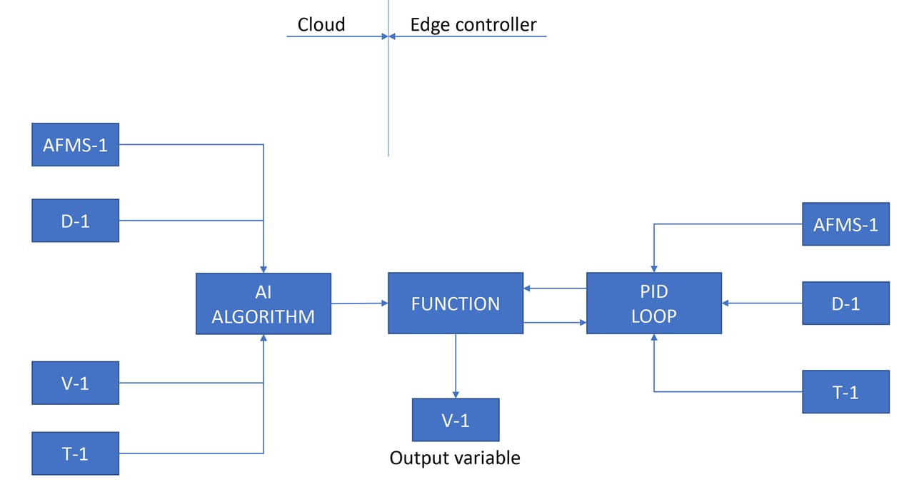
FIGURE 4: A sample control logic for an edge controller.
Ionel Petrus, P.E., CEM, LEED AP BD+C
Ionel Petrus is a licensed professional engineer who has more than 13 years of mechanical design experience. In addition to being the mechanical discipline leader in SmithGroup’s Washington, D.C., office, he is also a LEED AP and a certified energy manager. His experience includes designing HVAC systems for commercial buildings, research laboratories, health care facilities, and museums. He can be contacted at ionel.petrus@smithgroup.com.

[Traimak_Ivan]/[iStock / Getty Images Plus] via Getty Images