

feature
Modeling HVAC Hydraulic Cooling & Heating Systems
Modern computer modeling software is a powerful tool proven to identify the entire system operation and determine the best and safest design solution.
Large facilities utilizing HVAC hydraulic cooling and heating systems are incredibly complex. New design and/or modifications (expansion) of these systems, which are commonly utilized in pharmaceutical manufacturing, critical facilities (data centers), or hospitals, require complete analysis based on solid calculations for stakeholders to make decisions for functionality, safety, reliability, and cost efficiency. Traditional hand calculation or Excel spreadsheet programs cannot satisfy these requirements due to the nature of the method and the level of complexity involved. Modern computer modeling software programs, such as PIPE-FLO, are powerful tools proven to identify the entire system operation and determine the best and safest design solution.
Sample Large Chilled Water Cooling System Expansion
In a large facility, the chilled water (CHW) system usually requires a large amount of cooling capacity (see Figure 1). Each building has a distribution loop to serve end users, such as cooling coils, heat exchangers, etc. The campus usually has a central utility plant (CUP) serving several buildings, containing multiple chillers, pumps, and the associated expansion tanks, air separators, etc. As the campus grows, the CUP will need to be expanded as well.
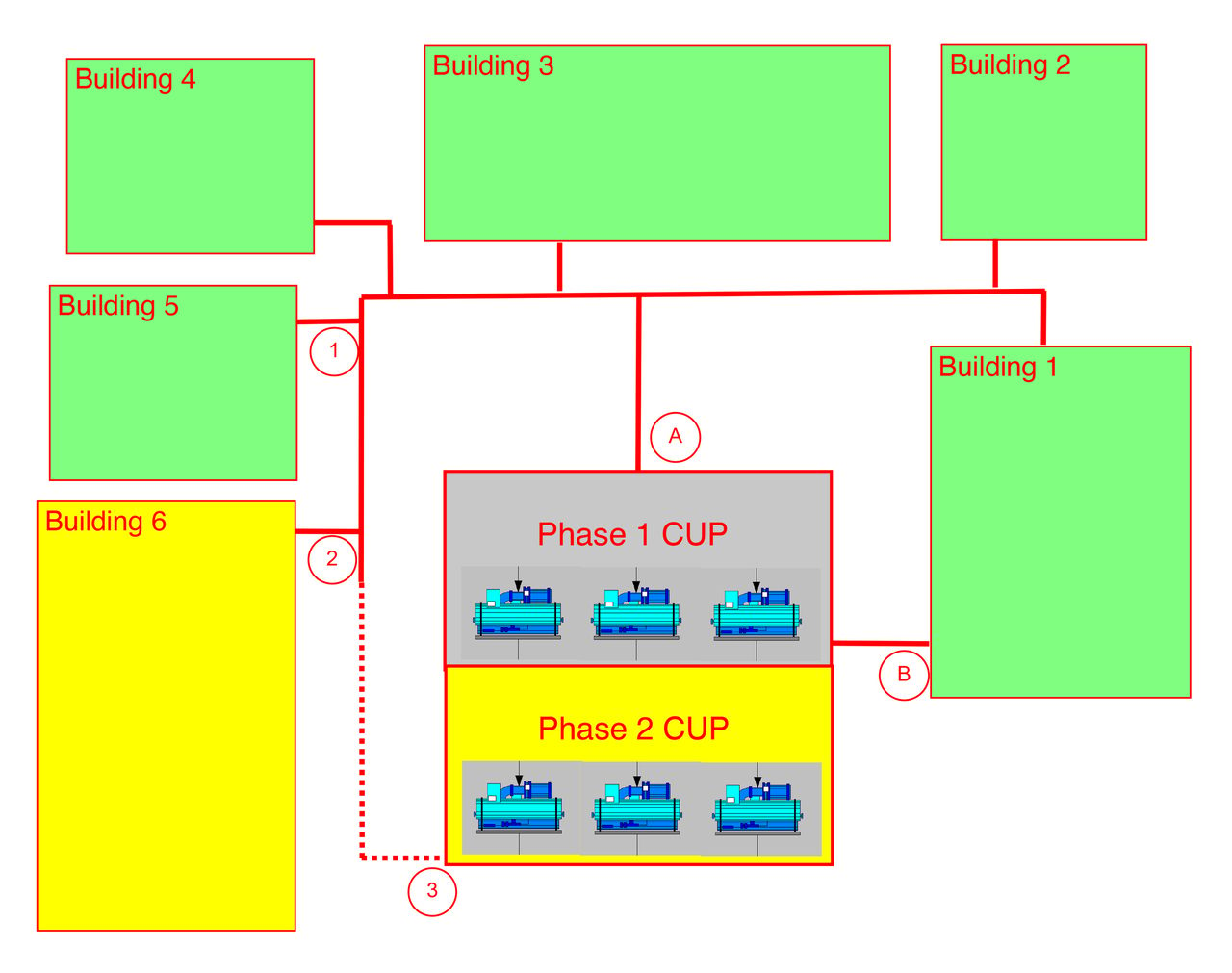
FIGURE 1: A sample chilled water system.
In the example shown in Figure 1, the phase one CUP serves existing buildings No. 1-5. Adding a new building (No. 6) will need extra cooling capacity provided by phase two CUP. There are two options for how the main piping system can service the new building:
Option one — Build chilled water piping from point one to point two, a single feed route; and
Option two — Extend piping from point two to point three to create a loop system.
Obviously, option two requires additional cost; the owner needs to know the benefit of option two and the potential risk of option one in order to decide between the two.
Traditional hand calculation or Excel spreadsheet programs are acceptable at calculating single pipeline friction loss but cannot handle this type of network calculation to offer the results as required. Every time a parameter changes, the existing building network will change the response, which then needs multiple calculations to find. Also, the method to calculate a looped system is very complicated for engineering work.
Evaluating option one with traditional Excel spreadsheet programs shows the existing piping from point "A" through "one" to "two" into the new building can handle the pressure loss with CUP one and CUP two's combined capacity. Similarly, the pumping system can handle the existing building users based on this type of single-piping line calculation. But this is all it tells us.
With hydraulic modeling software, we can model a large network piping system with all the necessary details. Such software can provide a clear picture of system performance, including pump performance and the operating condition/risk associated with each user (i.e., air handler coil and control valves), including flow rate, pressure drop, etc.
With PIPE-FLO, we completed several important tasks:
- Created detailed models of each building’s chilled water users and identified any potential risk caused by new system configuration;
- Tested the different connection pipe routes associated with option one and option two; and
- Adjusted the pump operating condition by changin speed, flowrate, discharge pressure, and/or differential pressure to test the system results.
For basic functions and the necessary input data, refer to the PIPE-FLO website (www.pipe-flo.com). From the model result, the following important items are identified:
- Under the same load condition, option one requires 18.8% more energy cost than option two (see Table 1). For simplicity, the utility price is 10 cents per kWH, assuming 100% peak load for one year. The real cost savings will be lower, as the chillers will run at partial load for HVAC units depending on the outdoor weather condition. PIPE-FLO can output an energy cost pie chart (see Figure 7) with detailed energy input, output, and usage on each component.
- With option one, building one has 42% higher differential pressure (dP) than the rest of the buildings. This is caused by the high discharge pressure from the new pumps in phase two CUP. This increase of dP will have to be absorbed by existing control valves at each user. This may cause issues in older, existing facilities besides waste of energy.
In addition to these, with a looped system, it provides redundancy for the entire system, as the CHW can be served in both ends of the CUPs, so if one end of the piping fails, the system can still work. This failure scenario is easily proven by a PIPE-FLO model using the “Lineup” function.
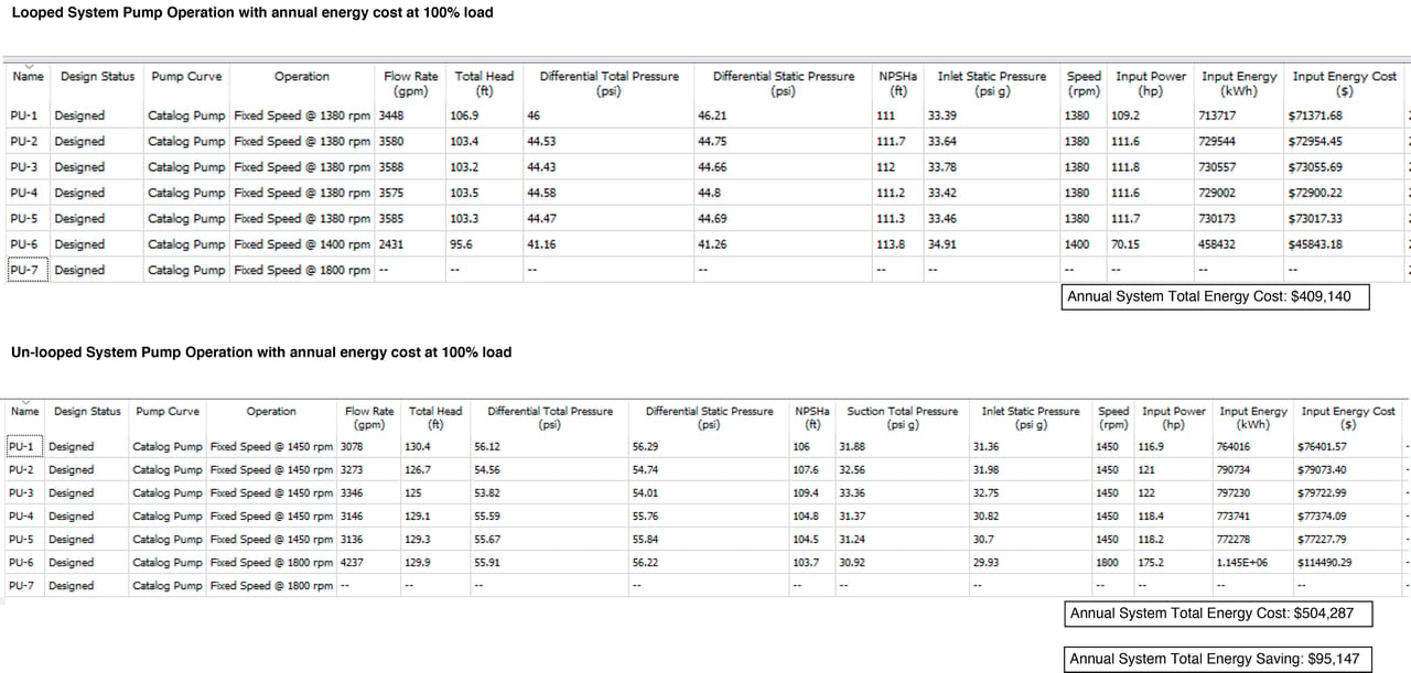
TABLE 1: An annual energy cost comparison.
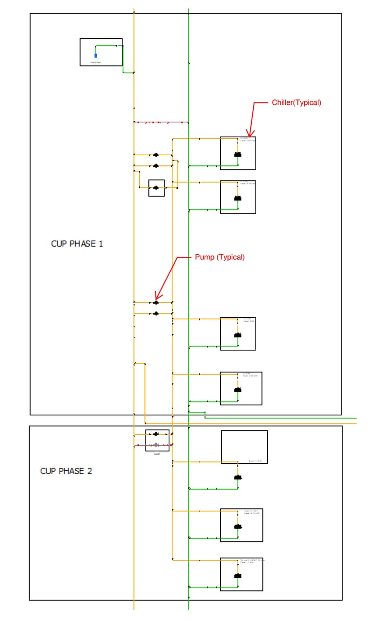
FIGURE 2: A sample CUP model in PIPE-FLO.
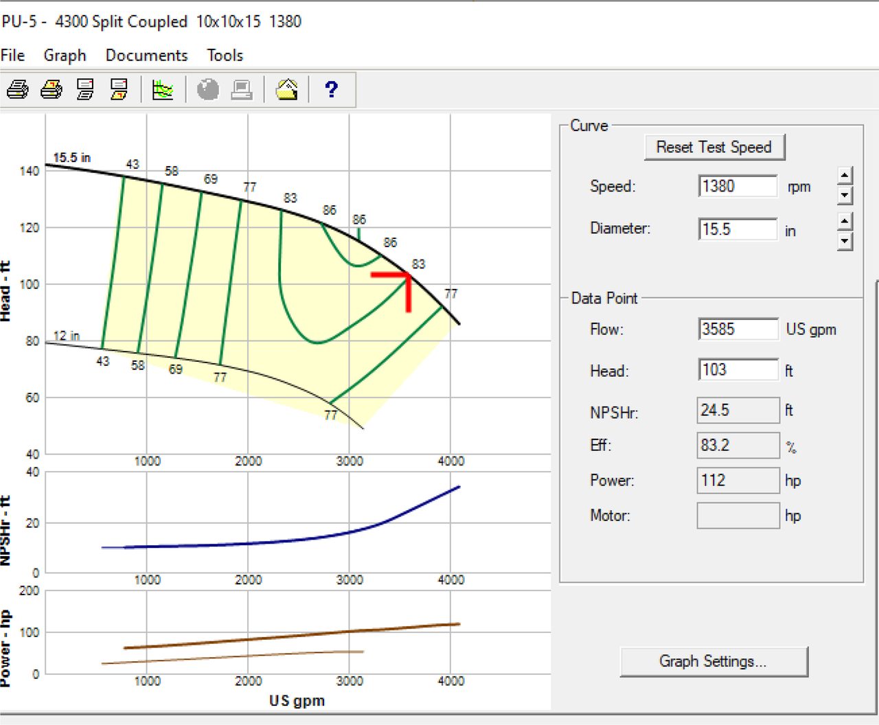
FIGURE 3: A sample pump curve from PIPE-FLO.
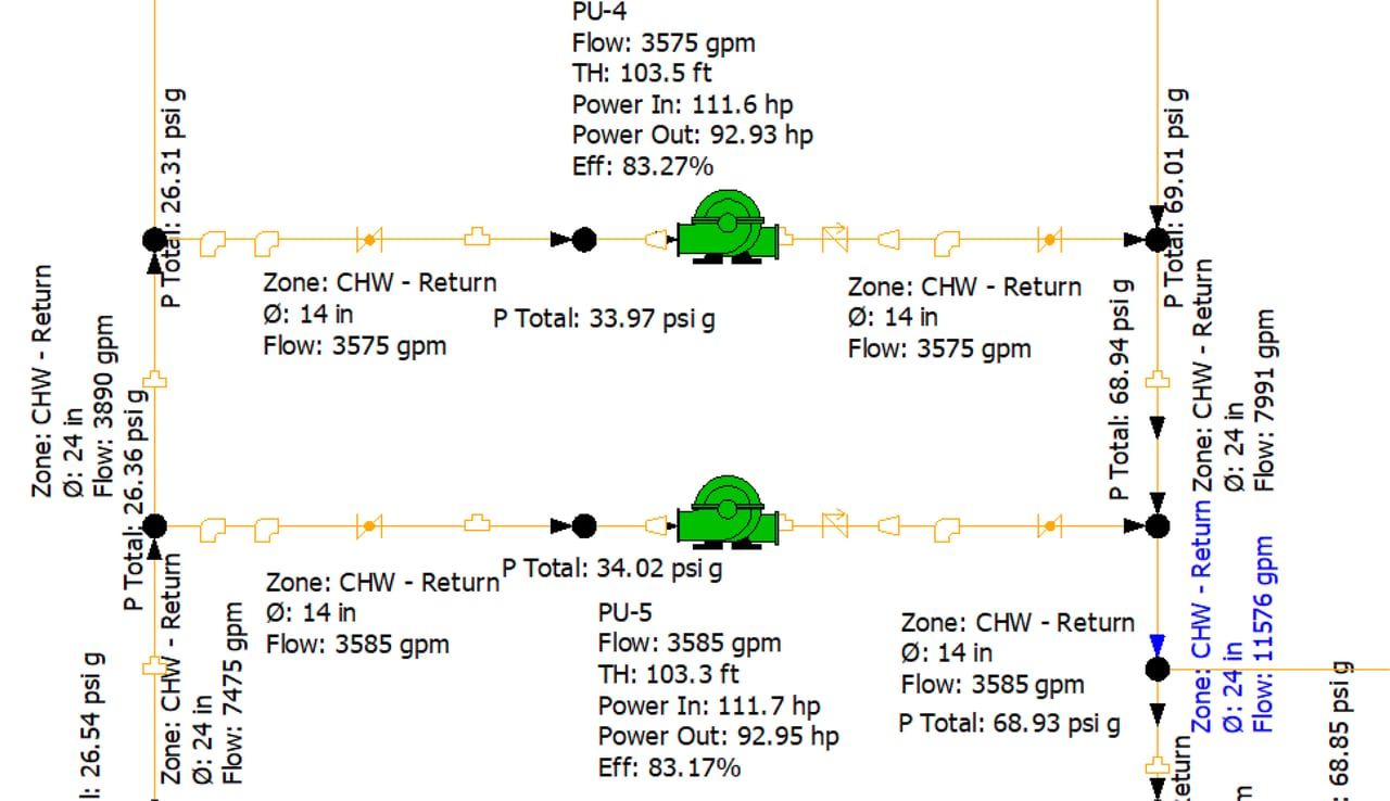
FIGURE 4: A sample pump arrangement.
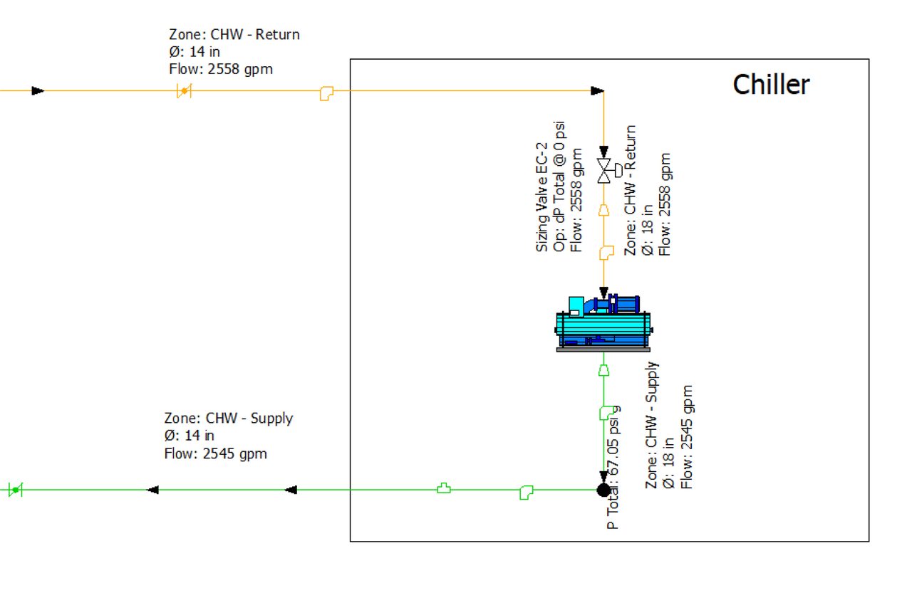
FIGURE 5: A sample chiller arrangement.
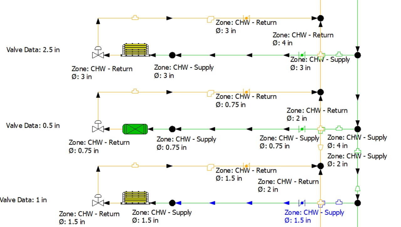
FIGURE 6: A sample end-user (air-handling unit/heat exchanger) arrangement.
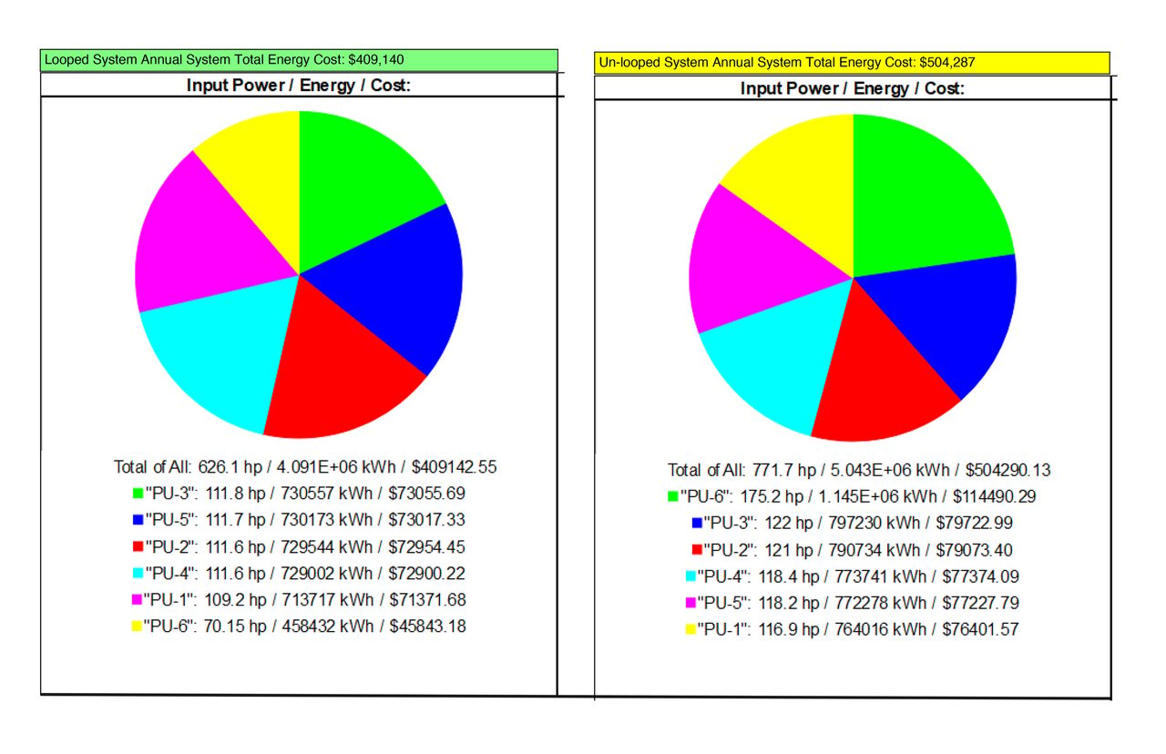
FIGURE 7: A PIPE-FLO output energy cost pie.
Conclusion
Computer modeling of complicated hydraulic systems is a strong tool to help HVAC engineers solve challenging questions in large facilities. When compared to traditional hand calculation and Excel spreadsheet programs, modeling can provide complete system calculations and return valuable results or warnings, so engineers can make sound judgements in short periods, which substantially improves the accuracy and efficiency of engineering design.

Haigang Brian Li P.E., CEM, ASHRAE HFDP, LEED AP
Haigang B. Li is a senior HVAC mechanical engineer with a master’s degree in mechanical engineering. He has more than 20 years of engineering experience in the building HVAC industry.
[AvigatorPhotographer]/[iStock / Getty Images Plus] via Getty Images