
SCROLL
Calculating Proper Raised
Floor Airflow
How to determine adequate subfloor plenum pressure in computer and electronic equipment rooms.
COVER STORY

SCROLL
Newer electronic equipment rooms, such as high heat density data centers and communication areas, may utilize cooling equipment equipped with newer technologies, such as in-row or in-rack cooling units. Sometimes, these units even include containment systems. However, there are lots of cooling systems still in use that rely upon computer room air-handling units (AHUs) with supply air directed down into a raised floor plenum. Often, these types of systems are not well understood by site personnel or the engineers who design them. This article will shed some light on the basics needed to understand raised floor plenums and expand upon their shortcomings.
During my time providing engineering for military communication sites, I often visited dozens of sites around the world and had firsthand experience with raised floor plenums. Site details in this paper are intentionally vague to preserve security needs.
Perhaps one of the most challenging aspects of this work was maintaining the floor plenum pressure at adequate levels to provide cooling to the communication racks that either had their cooling airflow directed into the bottom of the rack or into the front of the rack using floor registers within a cold aisle. Site personnel were often frustrated by racks overheating due to a lack of airflow, even though the air conditioners were adequately sized.
Hot Aisle/Cold Aisle Configurations and Limitations
When using floor plenums for rack cooling, experience soon showed that arranging racks that receive their cooling airflow from the front worked best if a cold aisle with outlets from the floor plenum discharged into this aisle only. The next aisle over received the hot exhaust air from the racks, an ideal place to pull return air back to the air conditioning units.
Floor outlets in the hot aisle are not required and actually are counterproductive. The hot aisle would also receive the exhaust from the next row of racks over and so on. So, one cold aisle may feed up to two rows of racks, and one hot aisle may accept rack exhaust air from up to two rows of racks, depending upon the layout.
This aisle configuration works well for lower heat racks but has limitations for higher heat racks due to the plenum’s inability to move the necessary airflow. This results in inadequate cooling at the rack and the recirculation of air from the hot aisle into the cold aisle. Close coupled cooling technology with containment systems works well for high-heat racks since it provides a cooling source right at the load and prevents recirculation of hot air into the inlet of the rack.
Pressure Units
When dealing with air pressure in air conditioning systems, it’s conventional wisdom to use inches of water column (in. wc) units. One can make a simple manometer by taking some clear fish tank tubing and bending it into a “U” shape. If one end is placed into the floor plenum and the other is left in the room, one can obtain the floor plenum static pressure by measuring the height difference of the water in the tubing. In practice, this method is handicapped by the very low pressure in the plenum, and it is best to have a digital manometer that is capable of low pressures at or below 0.1 in. wc.
Floor plenums typically are very low-pressure chambers, and pressures above 0.1 in. wc are not very common. I found nearly all of the sites I visited had plenum pressures ranging from near zero up to 0.1 in. wc, with most falling into the 0.03-0.05 in. wc range. Only one site had a pressure more than 0.1 in. wc in over two decades of field work.
What Is Really Going On?
In a well-designed plenum, plenum pressure is determined by the floor grille area, which, in turn, determines the air velocity flowing out of the floor grilles. The interesting part of this is it is not a linear function, rather a squared function. The pressure loss across the floor outlet is proportional to the velocity pressure. Velocity pressure is proportional to the square of the velocity.

Pv = velocity pressure measured in in. wc
V= velocity in feet per minute
4,005 is a unit conversion factor for sea level conditions
As an example, for a given airflow into the floor plenum, if one doubles the number of floor grilles (thus doubling the outlet area and reducing the outlet velocity by half) the plenum pressure goes down by a factor of four.

I was able to demonstrate this during an engineering class for our subcommands by using a well-sealed cardboard box with X number of holes about 1 inch in diameter. The box was fed by a small centrifugal fan. A digital manometer measured the static plenum pressure. When the number of holes was doubled to 2X, the plenum pressure dropped to one-quarter of its original static pressure.
This amazingly simple engineering principle is the key to plenum pressure analysis.
One time, while working on a site in Europe, the floor plenum pressure was very low, causing loss of cooling at the racks. So, the designer was contacted indirectly by the site personnel. The designer’s answer to the problem was to call for replacing the existing computer room air conditioners (CRACs) with new units with an increased fan output pressure from the usual 0.1 in. wc to 0.2 in. wc with the same flow rate.
The designer was obviously unaware of the above fundamentals of plenum pressure.
The real answer was to carefully analyze the number of outlet grilles and reduce their quantity in order to increase the plenum pressure. This was accomplished by removing unnecessary floor outlets (those not in front of equipment racks), including any in the hot aisles (floor outlets in the hot aisle are counterproductive and actually reduce the capacity and efficiency of the air conditioning system since cooler air back to the cooling units increases their thermal lift to the outdoor air condition). See the “Hot aisles should be hot” section for more information about this.
Airflow into the floor plenum is typically set by the heat load of the electronic equipment, lighting, etc. as well as the thermal load of the envelope. Should your site be in a hot desert climate, the soil temperature will also induce a heat load into the plenum. Consider using insulation for the plenum areas to minimize this heat gain. Since the airflow is fixed by the load, the real key to the plenum pressure lies with the outlet area of the floor grilles. One must always keep in mind that the plenum pressure is not linear with floor outlet area; rather, it is a squared function as noted above.
Another approach, perhaps more unique to older military communication racks, is to discharge air directly into the bottom of the equipment racks. While very efficient, some racks had no or minimal heat load, yet they had large openings into the floor plenum. This obviously allowed precious cooling air in the plenum to vent directly to the room without doing any rack cooling. This also had a major impact on plenum pressure.
The approach provided with these types of racks was to measure the delta T across the rack and provide field-rigged dampers in the base of low-heat racks. The dampers were adjusted to provide the vendor-specified air temperature at the top of the racks or the delta T as specified by the vendor.
Passive racks without any heat load were blocked off from the floor plenum. For low heat racks, this meant a substantial reduction in the airflow into the rack, which preserved the cooling airflow needed for the higher-heat racks. This was a reiterative process usually requiring several passes to stabilize the system.
I adopted the term “rack airflow management” and provided a detailed instruction set for the field to use along with assistance from our engineering group.
How Do I Know How Many Floor Grilles to Use?
The aforementioned information is great if you are dealing with an existing facility and are simply adjusting floor grille quantities to improve the plenum pressure. If you’re faced with knowing how many floor grilles to use for a new installation, the floor grille vendor typically has some rules of thumb for the number of outlets to use based on how many tons of cooling are employed. This approach usually assumes 0.1 in. wc in the plenum.
By the way, tons of cooling got its start during the early days of air conditioning, when ice wagons would deliver ice to buildings using fans to blow air over ice blocks to deliver cold air to the space. If the ice wagon would deliver, say 10 tons of ice a day, this is equivalent to a modern day 10-ton air conditioner. One ton is equal to 12,000 Btuh or 3.52 kW.
Computer rooms typically don’t have much of a latent heat load if they’re well designed. This means the heat load is nearly all sensible and flows of 600 cubic feet per minute (cfm) per ton are not unusual. This higher airflow keeps the cooling coil warmer, reducing moisture removal and increasing sensible heat transfer. Higher flow rates are needed at higher elevations to preserve the equivalent mass airflow rate due to the lower density air at higher elevations.
So, back to the question of how much floor grille area one needs for a new installation. I’d recommend additional consulting with the floor grille vendor if one wishes to take a step further than the rule-of-thumb method. A selection equipped with the necessary pressure drop to keep the floor plenum at the desired pressure while recognizing the flow will tell you how many grilles are needed. As noted before, a typical goal is to design for a plenum pressure of 0.1 in. wc. The plenum pressure can be fine-tuned during commissioning. Be sure to order extra floor tiles to replace any tiles with floor registers removed during this process.
Hot Aisles Should Be Hot
To provide a bit more detail about why floor grilles in hot aisles is a bad idea, it’s beneficial to use a water well analogy. Air conditioners move heat from a low temperature (in the cooling coil) to a higher temperature (in the condenser), where refrigerant is condensed back into a liquid.
Let’s assume you now have a water well with a bucket and a rope, and you are the power source to lift the water out of the well. Like the air conditioner, you are moving water from a lower level to a higher level.
Back to the hot aisle now … if the air leaving the hot aisle is warmer, it reduces the thermal lift needed to move the heat to the outdoor air condition. This would be the same in the water well as lifting the water from a higher level in the well to the surface. You expend less energy to move the water and can also move more water in a given time period, meaning you gained some capacity as well as efficiency.
Well-Designed Plenums
I used the term “well-designed plenum” earlier in this article. This implies the plenum is designed with enough depth to minimize friction loss as the air moves across the plenum from the outlet of the CRAC to the floor grilles. Thus, plenum depth is a key ingredient to a fairly uniform plenum pressure across the floor. I have found many floor plenums that are only 6 inches deep with resulting static pressure variations throughout the floor. This often results in loss of airflow at the more remote floor grilles. Floor plenums should be at least 24 inches deep whenever possible. More depth is better, and 30-inch depths are not uncommon, especially for larger areas or higher heat loads. Computational fluid dynamics (CFD) analysis may be needed for extensive and/or critical areas, but this requires a high level of expertise and experience. There is a lot of guidance available for general locations of the CRACs in relation to the rack layout.
CRAC with raised floor plenums is typically only viable for equipment loads below 100 W per square foot of room area as a general rule of thumb. Divide the uninterruptible power system (UPS) output by the raised floor area to obtain this value for existing systems. Use the actual rack heat load for new installs. Be wary of using the rack power supply value since power supplies are rated for the instantaneous startup load. If unsure, look for actual Btuh values and convert them to kW or ask for a steady state measured value.
Racks with 4 kW or greater have crossed the line into higher heat racks based upon my experience. Rack heats well above this threshold may be encountered.
Heat densities approaching this value (100 W per square foot for the room or 4 kW per rack), and those exceeding it, really need to be examined for alternative systems, such as in-row cooling with containment, liquid cooling systems, or other alternative close-coupled cooling approaches.
It is not uncommon to see both floor plenums and systems designed for higher heat density racks in the same room. In fact, even occasional high-heat density racks among lower-heat racks may not cool well using the floor plenum due to the localized loss of plenum pressure. This is due to the needed high-flow floor grilles as well as recirculation of hot air into the cold aisle. High-flow floor grilles cause a localized area of lower plenum pressure in their vicinity that reduces the cooling airflow through the floor grilles. An additional concern with higher velocities into the cold aisle is the slight reduction in static pressure that tends to induce flow from the hot aisle into the cold aisle. These situations are best addressed using close-coupled cooling methods, such as in-row coolers possibly including containment systems.
Should you encounter a situation where a piece of equipment has its own fan drawing air from the plenum, this flow needs to be subtracted from the calculated airflow for the room for plenum pressure calculations. Some of the sites I visited had fan-forced cooling from the plenum for transmitter racks. These racks were in a separate room with their own dedicated air conditioners.
Subfloor clutter in a plenum cooling system leads to a really bad situation. Once I was called to troubleshoot a communication site in the Middle East. As I walked onto the communication floor, I noticed the raised floor tiles were not solid but moved as I walked across them. Curious, the site chief was kind enough to fetch the floor tile puller, and when we lifted the floor tile, the spaghetti-like cabling below the floor actually sprung up slightly when the tile was lifted. One could not even see the concrete floor below due to the incredibly dense mass of cabling beneath the floor. I think that was one of the shortest troubleshooting sessions I ever had. The airflow from the CRAC was essentially blocked due to all the cabling, resulting in the room overheating. My job was finished, but the cable dogs had their work cut out for them.
Minimizing or eliminating cable runs in raised floor plenums makes for well-designed plenums. Be sure to minimize any piping near CRAC outlets.
Minimize Leaks
Keeping the floor plenum tight requires good maintenance to ensure the floor grid is level, clean, and well-sealed at the floor tiles. Pay particular attention to the cables, columns, and pipe penetrations being sealed. The floor perimeter should also be inspected and, if any leaks are located, they should be sealed. A tight floor plenum should have only 2% leakage. Excessive leakage has more impact than most realize due to the squared function on pressure in the plenum.
Floor Grilles Suck Sometimes
This brings to mind another incident when I was working on a site on the East Coast. The air conditioning tech approached me cautiously and said the site folks thought he was crazy. I asked him what that was all about. He took me over to a floor grille about 3 feet away from a large down-flow CRAC and asked me to check the exiting airflow.
One simple way to do this is to throw a sheet of paper over the grille and see how far it lifts up. Now, I recognize this is not very scientific, but it gets the job done for relative airflow rate. The tech was very animated when the sheet of paper stuck to the grille like glue. Then, he said, “See, I’m not really crazy. That grille is sucking air in rather than blowing air out.” Apparently, the site folks thought this scenario was impossible, and they were riding him about his sucking floor grille. I checked the plenum depth by lifting an adjacent floor tile, and it was only about 6 inches deep.
Due to the very shallow floor plenum and large adjacent down-flow air conditioner, the velocity of the air parallel to the floor was high enough to cause the plenum static pressure to go negative relative to the room near the unit. Recall your physics professor talking about Bernoulli and this scenario makes more sense. Fast-moving air loses static pressure.
A similar situation that is more familiar is riding in a car at highway speed with a window slightly cracked. If someone is smoking in the car, the smoke will drift over to the partially open window and get sucked out. The high-speed air flowing outside the window reduces the static pressure, causing the smoke to get violently ripped out of the vehicle through the cracked window. This same scenario is also responsible for airplane wings having lift when the air flowing over the top of the wing is going faster than the air going under the wing due to the shape of the wing.
As the airflow moves away from the CRAC radially, it will slow down due to the increasing area of the floor plenum. The area the airflow sees in the plenum is:

A = area in square feet
π = 3.1416
R = radius away from the center of the air conditioner outlet in feet
D = depth of the floor plenum in feet
Notice that as the radius increases, the area the airflow sees increases, resulting in the airflow slowing down and gaining static pressure. This equation assumes the CRAC is not against a wall or major obstruction. The math majors will recognize the first part of this equation as the circumference of a circle, with the center of the circle at the air conditioner. Multiplying that circumference by the depth of the plenum gives the area in question as the airflow moves away from the unit.
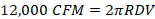
Let’s assume we would like to know where the plenum pressure just turns from negative to positive relative to the room. Assuming the distant velocity in the plenum is minimal, one way to get an approximation of this value is to determine where the velocity pressure just equals the desired plenum pressure, assuming the velocity pressure is converted to static pressure in the plenum efficiently. The unit flow rate is 12,000 cfm for the above example. For a plenum with a desired pressure of .08 in. wc, we would like to know when the Pv equals 0.08 in. wc. See Equation 1. Working the math yields about 1,133 feet per minute.
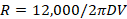
Flow = area x's velocity
R = radius from the CRAC outlet in feet
D = 0.5 feet
V = 1,133 feet per minute
Solving for R yields 3.4 feet assuming efficient static regain from the velocity pressure. This is the approximate distance from the CRAC, where the plenum pressure just equals the room pressure or zero delta P across the floor. As the air continues to slow down from this point on, the static pressure in the plenum will build to 0.08 in. wc if the air velocity slows to near 0 with efficient static regain. Once again, this is just an approximation to give one a feel for the distances involved. Note that a deeper plenum minimizes pressure variations in the plenum.
Only Run Redundant Air Conditioners if They’re Needed
I visited a site once where the site chief was complaining the temperature in the floor plenum was above 60°F. 60° was the maximum allowed plenum temperature for his equipment racks. His racks were open on the bottom and fed cooling air directly from the floor plenum. I toured the facility and discovered that both of the backup air conditioning units normally used, should a primary unit fail, were on. This configuration is called N+2 redundancy, where N is the number of units needed to cool the space. Since the load was easily carried by the primary units, two units in the area were pumping warm room air into the plenum, causing the warmer plenum temperature.
I bet the site chief that I could cool his plenum down within five minutes. He took the bet, and I walked over to the backup units and turned them off. He instantly got very excited and was about to throw me out of the place. Outages in military communication sites can be devastating, so his reaction was understandable. I convinced him to measure the plenum temperature once again, and he discovered it was now within specification. The downside was he lost some plenum pressure, so his site was an immediate candidate for rack airflow management that proved to be very successful. Site personnel were running the redundant units in an attempt to improve the plenum pressure. Rack airflow management not only improved the plenum pressure above what they had achieved by running the redundant units, but it improved rack cooling, increased reliability, and reduced energy consumption.
Minimize 'Fighting' Among the CRACs
Although not directly related to plenum airflow basics, this topic is usually commonplace in many computer room facilities, so it is worth discussing. It is not uncommon when walking through a computer or electronic equipment room to find one CRAC cooling and dehumidifying and the next one over humidifying. Variations on this theme also happen with the commonality that the units are fighting each other, wasting capacity and energy.
Sensor drift is partially responsible for this since one humidistat or temperature sensor may register a different value than another one in another unit. Even if sensor drift isn’t responsible, variations in air temperature and humidity within the space can trigger similar fighting scenarios.
The best way to remedy this scenario is to have a common control system for multiple units to keep them all pulling in the same direction while eliminating individual unit control. This also allows controls to automatically activate backup units should a primary unit fail as well as rotate the units in operation.

Bruce Johnson, P.E.
Bruce Johnson is a retired mechanical engineer. Contact him at bruce4795@gmail.com.
[piranka]/[E+] via Getty Images