
Pumps and Flow Controls in Large Chilled Water System Startup
For large hydraulic heating and cooling systems, modern computer modeling software can be used to determine the system operation conditions during startup while the system only has a partial load.
FEATURE
SCROLL
Chilled water system expansion for large facilities sometimes can be quite complicated; it may be even more challenging to startup the new subsystem when there is only partial loads at day one.
Upon the completion of construction, the chilled water system is ready to run; however, the users may not be ready to run at the same time, which means we have to start the system in phases. It requires the commissioning team to balance the new subsystem without impacting any other subsystems while also satisfying certain specific criteria, such as minimum velocity.
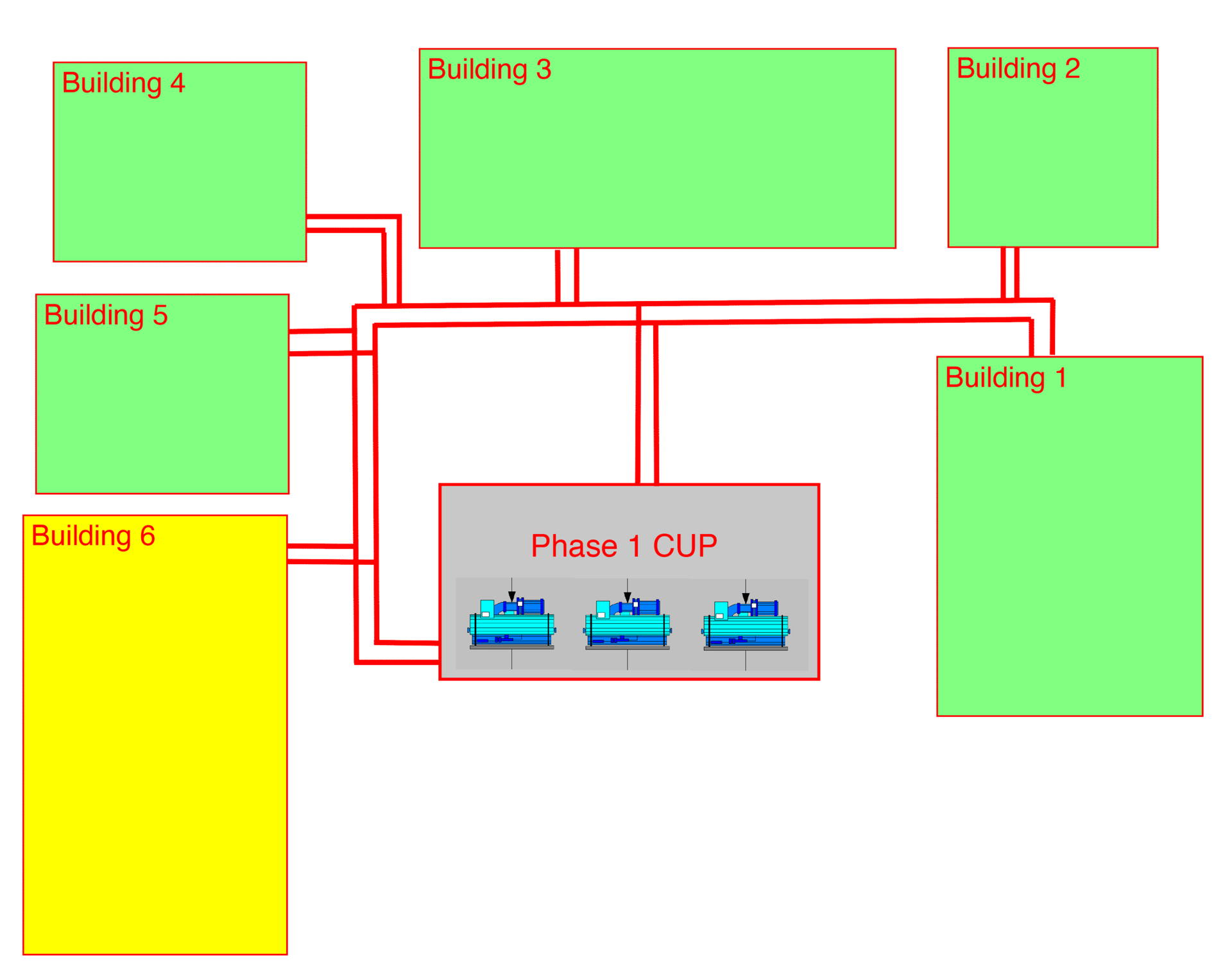
FIGURE 1: All chilled water pumps in the central utility plant (CUP) are controlled by maintaining differential pressure (DP) at the CUP main headers to satisfy each individual building’s demands.
Image courtesy of Jacobs
Modern computer modeling software, such as PIPE-FLO, proved to be the right tool to identify the entire system operation and determine the best and safest approach.
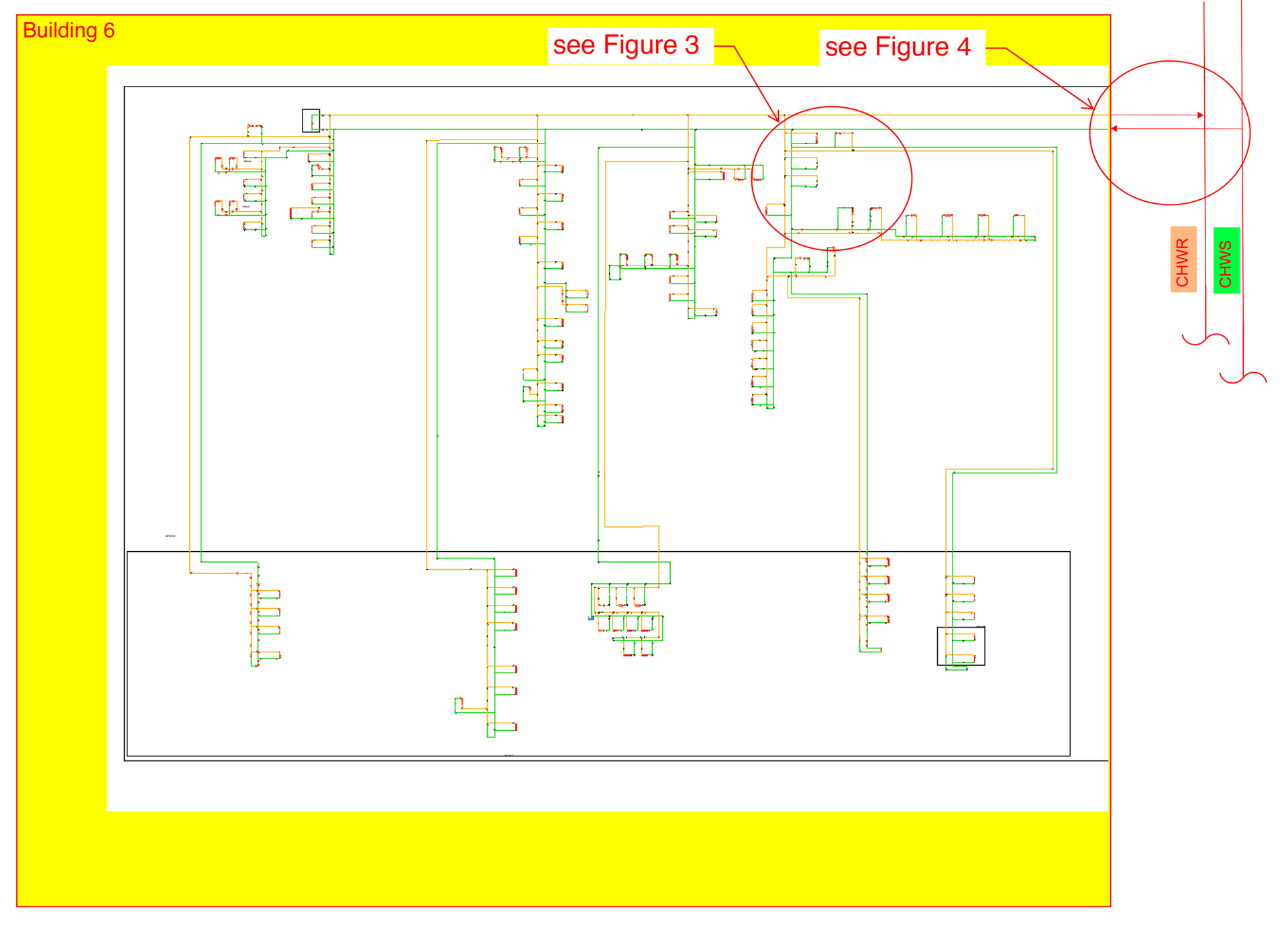
FIGURE 2: The structure featured here, Building 6, is a new structure that is comforted via an expansion of the existing chilled water system.
Startup of Large Chilled Water System Expansion
A large facility usually has a central utility plant (CUP) serving several buildings. The CUP has multiple chillers, pumps, and associated expansion tanks, air separators, etc. In Figure 1, Building 6 is a new structure that is comforted via an expansion of the existing chilled water system.
There are multiple control strategies for chilled water pumps. In this example, all chilled water pumps in the CUP are controlled by maintaining differential pressure (DP) at the CUP main headers to satisfy each individual building’s demands.
As Building 6 is ready for commissioning, only about 30% of the internal users are ready to operate for testing and balancing (day-one load equals 30% of the design load).
With computer modeling software, such as PIPE-FLO, the day-one load condition can be simulated in detail (see Figure 3). The users who are not ready to operate on day one can be “closed” in the model, and the different load scenarios can be easily modeled, so we can find the hydraulic data, such as DP, total flow rate, etc., as needed.
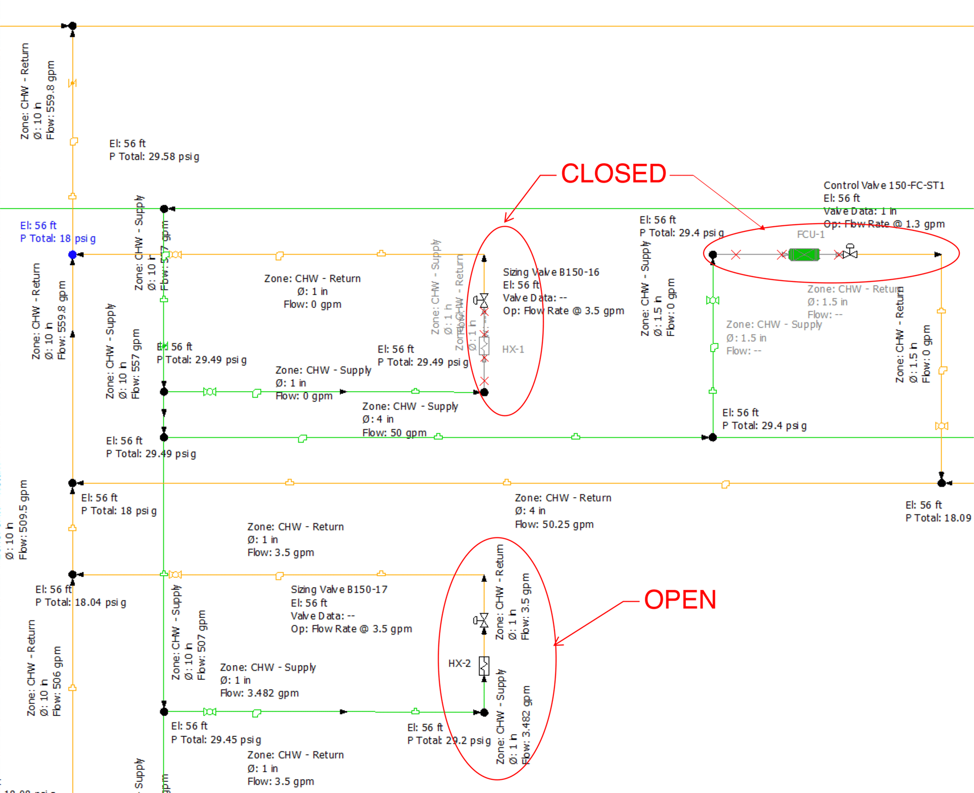
FIGURE 3: With computer modeling software, such as PIPE-FLO, the day-one load condition can be simulated in detail.
Several approaches shall be followed to achieve day-one testing and balancing:
- In order to keep the existing buildings’ chilled water system operation running as usual, Building 6 has to maintain a similar DP at the main branches coming into the building. As the system design is to meet the similar DP during 100% load, with 30% load (both chilled water flow rate and building DP) at day one, extra internal pressure drop needs to be created by adjusting the control valves at the main branches. (see Figure 4.)
- Partially dialed-down main control valves (or butterfly shut-off valves) can achieve the extra DP to match the extisting campus's DP.
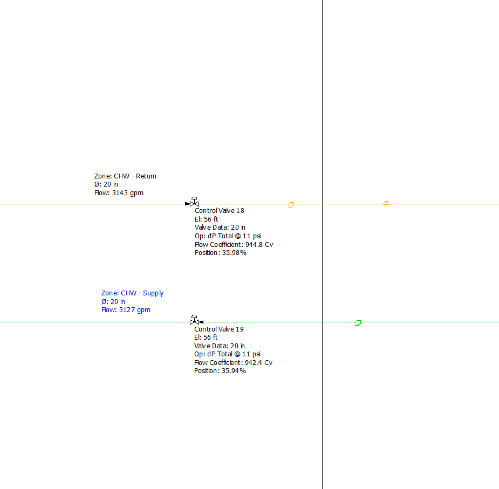
FIGURE 4: As the system is designed to meet the similar differential pressure (DP) during 100% load, with 30% load (both chilled water flow rate and building DP) at day one, extra internal pressure drop needs to be created by adjusting the control valves at the main branches.
With the simulated partial load, we can predict the flow rate and DP at the main pumps in the CUP, so the operation team can adjust pumps in advance as necessary to accommodate the new building startup. This will prevent an unexpected surge of DP or flow rate during new system tie-in. This procedure can be repeated for the following commissioning phases until the new building is fully operated at 100% load.
It is recommended to have a bypass at the end of the main loop during startup, so extra flow can go through.
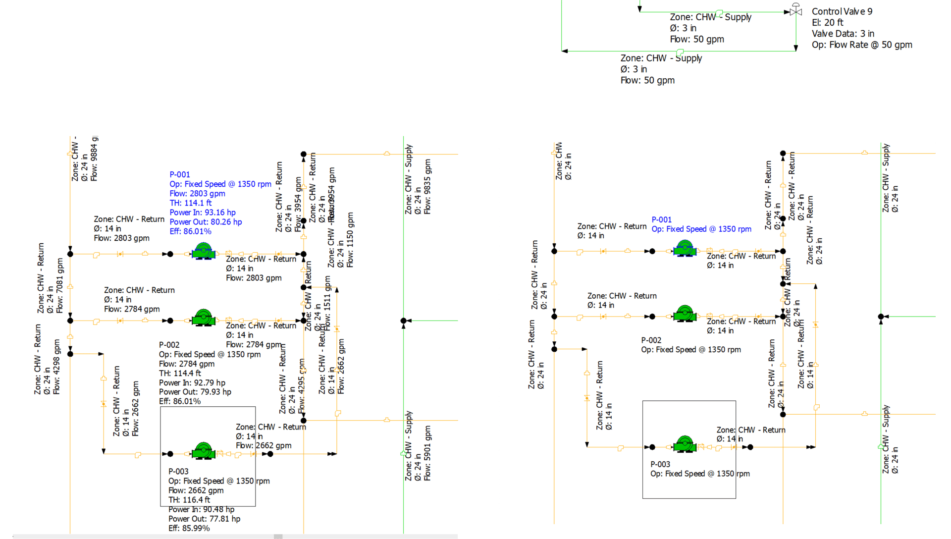
FIGURE 5: In some cases, minimum chilled water velocity is required to prevent chemical corrosion; it can be achieved with the bypass at at the end of loop. With a PIPE-FLO model, it is easy to find the valve position at the required velocity.
In some cases, minimum chilled water velocity is required to prevent chemical corrosion; it can be achieved with the bypass at at the end of loop. With a PIPE-FLO model, it's easy to find the valve position at the required velocity.
The prerequesite of the above analysis is to fully understand and accurately model the entire chilled water operation, including the sequence of operation, piping and fitting arrangement, user equipment and valve data, etc. PIPE-FLO has a built-in library for pumps and estimators for valves, so we can either choose the equipment that most closely matches what is installed or manually input data. Extensive knowledge and experience with hydraulic systems is also required to achive accurate solutions.

Haigang Brian Li, P.E., CEM, ASHRAE HFDP, LEED AP
Haigang B. Li is lead building mechanical engineer with Jacobs. He has more than 30 years of engineering experience in the building HVAC industry.
[alacatr]/[E+] via Getty Images