
SCROLL
Seeking Ideal Hydronic Control
Are you using the ideal hydronic balancing and control valves?
COVER STORY
SCROLL
Are you using the ideal hydronic balancing and control valves? This article offers an overview of several balancing and control valves for hydronic systems along with benefits and rough cost comparisons. It will also cover a common misconception regarding use of automatic balancing valves (ABVs). This review begins with manual balancing valves paired with standard control valves. Discussion of ABVs and pressure independent control valves (PICVs) will occur later. For those familiar with hydronic balancing and valve selection, you may prefer to skip down to the ABV discussion.
Introduction
When there are parallel flow paths through the coils in a system, flows must be balanced by adding appropriate resistance to each coil path in the system. That way, each path receives the intended flow to accomplish its purpose. In variable flow hydronic systems, each flow path requires a means for balancing the system at design flow and a means for controlling (varying) the flow as the load changes.
Balancing valves are used to set a maximum flow through their coil’s flow path. Control valves intelligently increase or reduce flow to meet their coil’s current demand for flow. Commonly, a manual or ABV is paired with a control valve on piping to each coil to accomplish this. PICVs are another option, as they offer the benefit of acting as both a balancing and control valve all in one body.
Basic Versus Characterized Valves
Basic (non-characterized) versions of the valves used in hydronic systems do not slowly allow increased amounts of flow as the valves are opened. Rather, a small stroke in valve position from closed to partially open will allow a disproportionately large amount of flow through the valve body. (Stroke is referring to the travel of the valve when being moved or actuated. A quarter turn ball valve is stroked 90 degrees to go from closed to fully open.) Likewise, adjusting the valve position when near its full open position will have little effect on the flow allowed through the basic valve. This occurs because the change in area through the valve opening (and thus flow coefficient, Cv) is not linearly related to the percent change in the valve stroke. This poses a challenge to flow balancing and control, since small changes near the closed positions have big effects and can make it hard to dial in the correct flow.
Calibrated or characterized balancing valves add a characterizing shape to the valve’s flow area. Characterized manual balancing valves are frequently referred to by Bell & Gossett’s trademarked name, “Circuit Setters.” However, characterizing shapes are used in both balancing and control valves. The characterizing shape alters how much area is available for flow throughout the valve’s stroke. A small stroke of the valve translates to a small increase in the amount of flow area. While characterizing causes a restriction to the maximum flow through a fully opened valve, it makes balancing more effective across the whole stroke of the valve. Calibrated control valves are also necessary to provide proper flow control.
There are different characterizing shapes that can be built into the valve. Common valve characteristics include quick opening, linear, and equal percentage. Refer to Figure 1 for a visual comparison between these three characteristics.
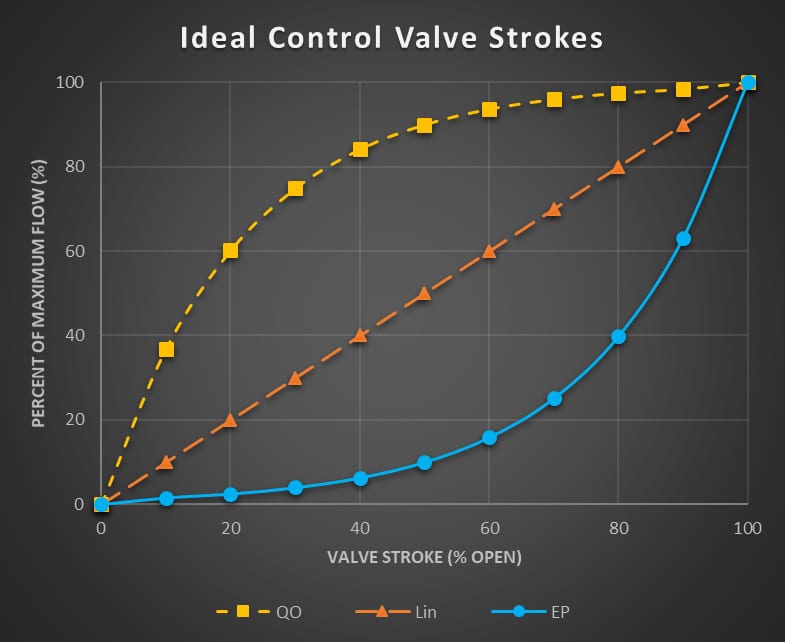
FIGURE 1: Ideal control valve strokes, flow versus valve stroke.
Images courtesy of WSP
The quick opening (QO) characteristic is generally how a basic, non-characterized valve acts. Movements closer to the closed position will yield big changes in flow. Movements closer to the open position will yield minimal changes in flow.
- This is great for two-position and isolation valve applications.
- These are not ideal for coil control valves. These valves would offer poor control with frequent hunting and overshooting.
- A linear (Lin) characteristic is self-explanatory. Equivalent strokes will yield equivalent changes in flow near closed, middle, and open portions of the valve position.
- For manual balancing valve applications, a linear characteristic is ideal so the balancer has proper tuning capabilities near both closed and open valve positions.
- Linear characteristic valves are not ideal for a coil control valve as discussed below. The relation between the amount of heat transfer versus flow through a coil resembles the quick opening valve characteristic (see Figure 2). Increasing flow through the coil adds a disproportionately large amount of heat transfer at lower flows. Ideally, a control valve’s percentage open would correlate to the percentage of heat transfer for that coil, but the quick opening and linear valve characteristics cannot provide this.
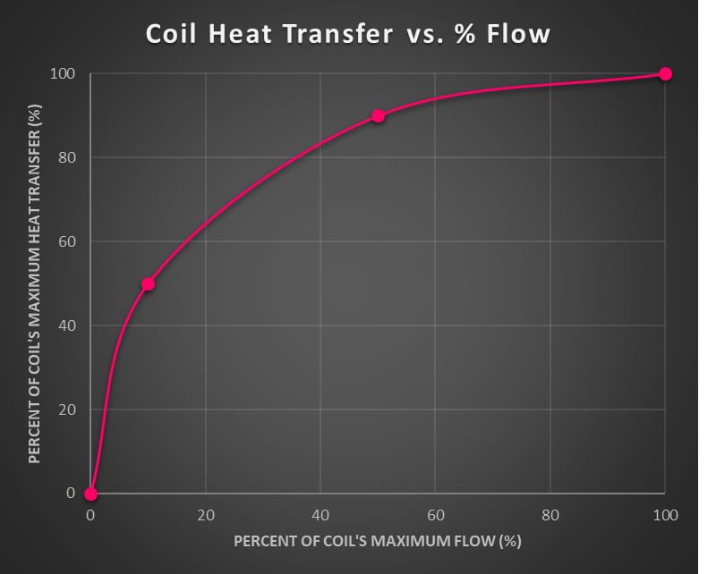
FIGURE 2: Coil heat transfer versus flow.
- You can think of equal percentage (EP) as the inverse of the quick opening characteristic. Movements near the closed position will create small changes in flow. Movements near the open position will create large changes in flow. These are generally preferred for control valve applications.
- Equal percentage valves are intended to provide an “equal percentage” increase in flow for every equal stroke in the opening of the valve. For example, if a valve is stroked 10% more open, the valve’s flow would theoretically increase roughly 60% relative to the flow before the stroke. Assuming we are observing a valve with a maximum flow of 100 gpm, this would hold true whether the 10% stroke was applied from 20%-30% open (2.5-4 gpm, respectively) or from 80%-90% open (40-63 gpm, respectively).
- The equal percentage characteristic is desirable for coil control valves. When an equal percentage control valve is used on a coil, the coil’s heat transfer versus flow (Figure 2) and the control valve’s flow versus position (EP in Figure 1) characteristics counteract one another. The outcome is a relatively linear characteristic between the coil’s heat transfer versus position of the control valve. A 50% open control valve will provide sufficient flow to give roughly 50% of the coil’s heat transfer capacity (see Figure 3).
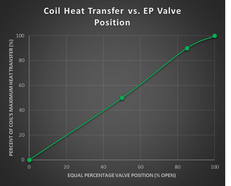
FIGURE 3: Coil heat transfer versus equal percentage valve position.
Control Valve Authority
These ideal valve characteristics can be observed when the valve has a constant differential pressure across the valve body as it opens and closes. In reality, the differential pressure across a typical valve’s body varies as valve position changes. This variation in differential pressure distorts the desired characteristic of the valve. The degree of distortion is referred to as the valve’s authority. Generally, authority is only scrutinized on control valves, since it does not noticeably influence balancing valve operation.
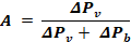
A = Control valve authority
ΔPv= differential pressure across the control valve when fully open
ΔPb= differential pressure across the other portions of the piping branch (piping, accessories, coil) with the control valve fully open
A valve’s authority ranges between 0 and 1. The value is a ratio between the pressure drop across the valve versus the pressure drop across the valve plus the valve’s branch (piping, accessories, coil, etc.). A valve with better (higher) authority will perform closer to the valve’s ideal characteristic. Valves with poor (low) authority will deviate from their ideal characteristics and respond more like a quick-opening valve. Low authority is a detriment for control valves. Control valves with poor authority hunt and struggle to maintain set points at low to medium loads.
Since a piping branch will always have some amount of pressure drop across it, a standard control valve is not able to reach a perfect authority of 1.0. A “proper” valve authority varies depending on who you ask. Generally, an authority below 0.25 deviates too far from ideal valve characteristics for useful control. Authorities above 0.5-0.75 offer great control, but may sustain too much of a pressure loss penalty, resulting in increased pump power. Bear in mind, these ratios pertain to standard control valves. PICVs break these norms.
It’s important to review the pressure drop of selected (and submitted) control valves to understand how the valve’s authority is impacted. There is a balance (pun intended) between selecting a higher pressure drop control valve to improve authority without going so high that you impose a significant energy penalty on the pumps.
Manual Balancing Valves
In addition to limiting authority for control valves, manual balancing valves have several drawbacks. First, the testing, adjusting, and balancing (TAB) process is very labor-intensive to manually tune all of the balancing valves in a system. Multiple measurements and iterations of valve adjustments are required to balance the whole system correctly. Anytime part of the system is altered, through renovations or additions, the rest of the system is impacted and must be rebalanced to return to intended flows. Also, it is not uncommon to find maintenance staff use balancing valves to shut off flow for repairs and not return the valve to the balanced position. Despite the drawbacks, manual valves are usually the cheapest option to purchase and install.
With the rise of variable flow systems, another problem with manual balancing valves became apparent. A variable flow system changes the system flow to match total demand and save energy on pumping. As control valves across the system open and close, the pressure across individual branches and valves varies from the pressure when the system was balanced. The system pressures will further vary as pressure set point resets occur for pump control. Since manual balancing valves are “pressure dependent,” they will drift from their intended flows when the differential pressure they see changes.
ABVs
Enter the ABVs. Sometimes these are known by other names, such as flow-limiting valves. The ABV automatically operates to maintain a constant flow through its branch of the hydronic loop. ABVs have an orifice “plate” or “cap” in the flow path attached to a spring. The orifice opening shape and connected spring are designed to reduce or increase flow area inversely to the differential pressure across the valve body. If the differential pressure across the valve increases, the flowing water applies more force onto the orifice. As a result, the spring retracts and pulls the orifice into the cartridge, which reduces the flow area available. Lowering the differential pressure across the ABVs does the opposite and exposes more flow area on the orifice. Each combination of orifice flow area versus pressure differential across the ABV results in approximately the same amount of flow until the spring becomes fully compressed or extended.
This ability to maintain intended flow regardless of the current differential pressure makes ABVs pressure-independent. They overcome the struggle manual valves have in a variable flow system. ABVs are also popular since they come from the factory with a specific cartridge set for the flow. There is very little TAB work for ABVs outside of verifying the correct cartridge is installed and validating the flow. ABVs are usually unaffected by system changes, such as renovations. The only time ABVs need adjustment is if the cartridge mechanism is not working or a different flow is required. This consistency among other reasons have given the ABV significant popularity as a balancing valve.
ABVs do have a few drawbacks. First, they cost slightly more to install than manual valves, but the increase is potentially offset by savings on TAB labor. Second, flow set points are incremental and nonadjustable. If a coil is specified to have 1.35 gpm of flow, but the ABV manufacturer only has 1.25- and 1.5-gpm options, then the balanced installation will underflow or overflow the design intent. Third, ABVs have a differential pressure range they operate within. Most standard ABVs have a 2-32 psi operating range but may also have options for lower (1-14 psi) or higher (5-60 psi) ranges for selection. Regardless of the selected pressure range, the ABV loses the ability to maintain flow when it sees a differential pressure above or below the range limits since the spring has fully extended or compressed. Fourth, control valves are still subject to authority issues even when paired with an ABV. Lastly and most importantly, ABV operation frequently impedes the operation of control valves.
The ABV's Weakness
ABVs automatically operate to maintain a constant flow, but they are frequently selected for use in variable-flow applications. It appears some specifiers expect ABVs to only limit the maximum flow through the coil, allowing the control valve to freely modulate from minimum to maximum flow. This is not the case; rather, the ABV fights the control valve to maintain a constant flow and counteracts a significant portion of the control valve’s stroke.
Imagine a standard VAV box with hot water reheat equipped with a standard control valve and ABV. At maximum (design) flow conditions, the control valve will be fully open, and the ABV will operate to maintain its selected flow. As the control valve closes to lower flow, the ABV will see a lower differential pressure across itself and begin opening (expanding the spring), which will maintain the flow at design. Since coil flow (and thus heat output) has not changed substantially, if any, the control valve will close further only to have the ABV offset the effort once again. This process repeats until the control valve has closed so far that the ABV reaches its fully open position at its low differential pressure limit and can no longer counteract the control valve closing. Only then will the control valve have regained “control” and be able to vary the flow.
Here are some basic numbers to help conceptualize this interaction. Let’s say the heating water loop operates at a 12-psi differential between supply and return lines, the control valve loss is 3 psi at design flow, and the coil plus piping kit loss is 1 psi at design flow. The remaining 8 psi of differential is absorbed by the ABV to maintain the flow at the ABV’s set point. To lower heat output from the VAV coil, the control valve closes to a position where the pressure loss across the control valve is 6 psi. The flow through the coil will be unchanged with the control valve absorbing 6 psi (at a partially closed position), the piping kit loss still at 1 psi, and the ABV adjusting to absorb 5 psi while maintaining design flow.
Only when the differential pressure loss through the ABV falls below its low limit (generally 2 psi) would the control valve finally throttle flow. In our example, this begins when the control valve absorbs more than 9 psi. Stroking the control valve from fully open (3 psi of loss) to partially open (9 psi of loss) has achieved little to nothing for reducing the VAV coil’s heat output. The control valve now must provide control for the whole flow range of the coil with only a portion of its stroke and a reduced differential pressure range (full flow at 9 psi to shutoff at 12 psi — see Figure 4.)
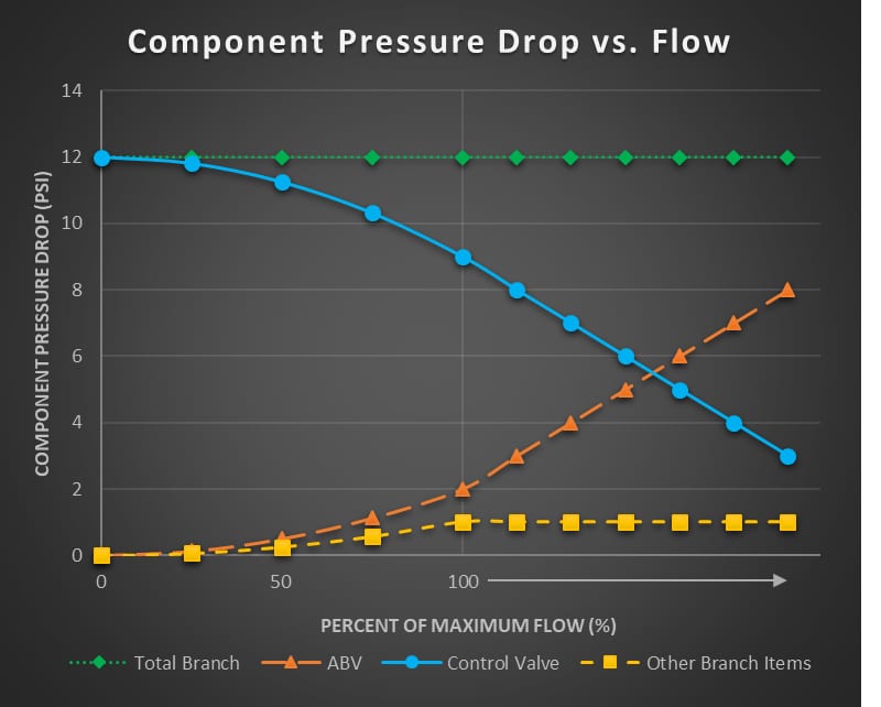
FIGURE 4: VAV component pressure drop versus flow through the branch.
ABVs used in a variable flow application can nullify a significant portion of a control valve’s stroke. The control valve will gain control sooner if the immediate differential pressure between supply and return lines is lower, the control valve is selected for a higher differential pressure at design flow, or the ABV low operating limit is selected at a higher differential pressure. Conversely, the control valve takes longer to gain control if it is selected for a lower design pressure drop, if the immediate differential pressure is higher, or the ABV is selected with a lower operating limit.
In general, differential pressure resets on the system will help ABVs relinquish control sooner. However, branches far upstream of the differential pressure sensor used to control the system pumps (branches near the plant) will see a significantly larger differential pressure between supply and return lines. Those control valves could be affected so much by their ABV that they begin to act more like a quick opening valve. Using an ABV effectively for balancing without impairing the control valve hinges on the ABV operating near its low differential pressure limit when at design flow.
The ABV in the above example would counteract the control valve until the control valve stroked below 75% open based on extrapolation from manufacturer literature. Bear in mind, this literature is based on ideal conditions (high valve authority) and a real installation with normal valve authority is expected to have a lower limit (roughly 65%-70% open) where the control valve regains control. However, other examples with the ABV operating near its low differential pressure limit at design flow could shift control to the control valve as high as 90%-95% open on the control valve stroke. The “regain control” limit will fluctuate for each valve depending on the specific valve used and other operating parameters. This counteracting effect by ABVs coupled with less than ideal control valve authority prevents control valves with ABVs from providing a linear relationship between coil heat transfer and control valve position.
PICVs
So, what other options can a specifier employ for hydronic balancing? Manual valves can suffer from mediocre authority and are labor-intensive to balance. ABVs counteract a noticeable portion of the control valve stroke. PICVs may be the solution.
PICVs take the balance and control operations and combine them into a single valve. The valve has a function to absorb a variable amount of system differential pressure to provide the design flow through the control valve at 100% open position. It has some similar components to the ABV, but, instead of a spring and orifice working to maintain a flow, the PICV spring and orifice work to maintain a constant differential pressure across the control valve ball or disc. So once a PICV is set, it will always have the same differential pressure across the control valve’s opening, regardless of valve position, until the spring is fully extended or compressed. If the system differential pressure decreases, the PICV spring expands to regulate a constant differential pressure across the valve and vice versa.
When seeing a constant differential pressure, a calibrated ball or disc can mimic the ideal characteristics discussed earlier. Recall our discussion on valve authority? Branch pressure no longer impacts the differential pressure across the throttling component of the PICV. Therefore, a PICV has an innate authority of 1.0. With a proper equal percentage valve characteristic, the coil’s heat transfer versus position of the control valve will roughly have a linear characteristic allowing optimal control of the coil.
Benefits and Cost Review
Now that functions of the various balancing and control valves have been reviewed, here is a summary of benefits, drawbacks, and costs for each option.
Several disclaimers to note: These cost approximations are for a complete coil piping connection with the indicated balancing and control valves. These costs only include the control valves plus a mechanical contractor’s direct costs for materials and labor to install the whole connection. No TAB effort has been factored into these. A single control valve manufacturer was used for these approximations. There were no significant changes in labor required for the various valve configurations, and the labor only increased for larger pipe sizes. These approximations were collected in May 2022, during a volatile market. Costs will vary based on the local labor market, inflation, supply chain, piping connection types, piping accessories, manufacturer, etc.
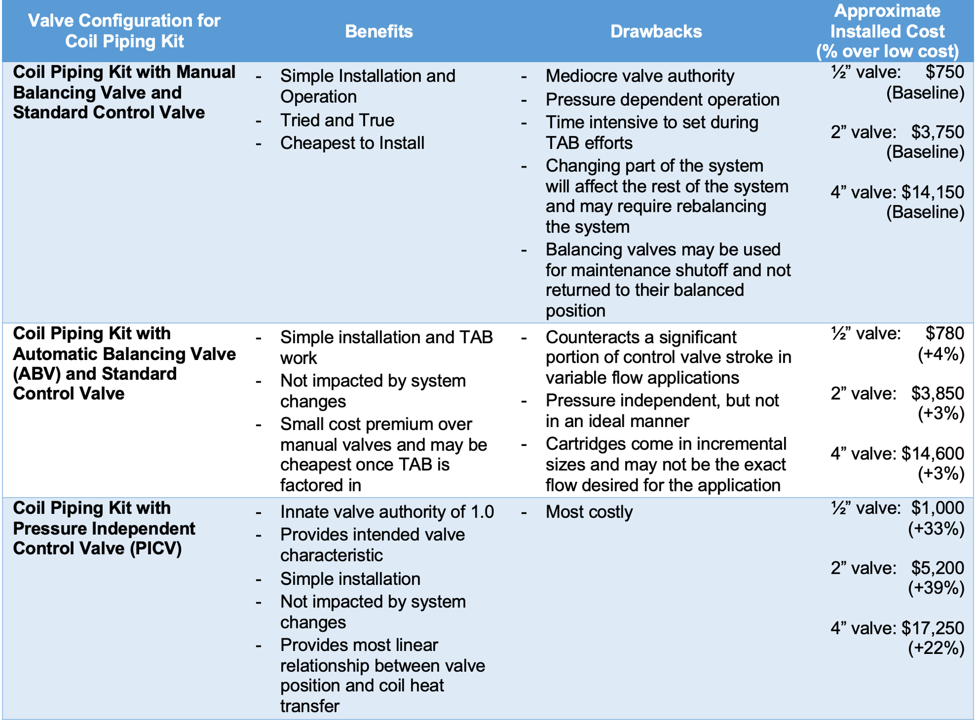
TABLE 1: Benefits, drawbacks, and costs of balancing and control valve configurations.
Summary
The goal of this article is to compare the operation of three common balancing and control valve setups used for coils in hydronic systems. The ideal valve configuration balances a coil’s maximum flow and creates a linear characteristic between the coil’s heat transfer output and the control valve’s position. This linear relationship offers ideal control capabilities so that a control valve at 50% position results in a coil with 50% output.
Manual balancing valves and ABVs paired with a control valve both have drawbacks:
- Manual balancing valves are pressure dependent and lower the control valve’s authority. These impact the control valve’s effectiveness and prevent ideal operation. Additionally, these are labor intensive to set and need to be rebalanced when the system is modified; and
- ABVs counteract a portion of a control valve’s stroke, preventing the control valve’s influence until the ABV has fully opened. This leaves the control valve with reduced stroke available to carry out its throttling responsibilities.
While they carry a cost premium, PICVs give ideal valve authority and control. PICVs can offer the desired linear relationship between a coil’s teat transfer versus position of the coil’s control valve. PICVs also make balancing simple and are unaffected by changing other parts of the system. Thus, I conclude, PICVs are the ideal control valve for hydronic systems.
Credits
Thank you to colleagues Rebecca Wiltz, Jackson Evans, Annie Fishback, Brandt Elledge, and Rodney Ashmore for assistance with content and reviews for this article. A special thank you to Jay Goode for mentorship throughout the article’s development and to Kevin Chow for the nudge to write.
References:
2020 ASHRAE Handbook: HVAC Systems and Equipment. Atlanta, GA: American Society of Heating, Refrigeration and Air-Conditioning Engineers, 2020. Print.

Michael Scott, P.E., CxA
Michael Scott is a licensed engineer with a degree in mechanical engineering from Texas A&M. He has served as lead mechanical engineer and project manager for many health care projects, including expansions and new hospitals over 200,000 square feet as well as 5,000-plus-ton chilled water plant replacements. He now operates as a leader for the commissioning team, lending his technical expertise on mechanical systems. Scott enjoys hunting, fishing, golf, and homebrewing beer when he has a moment to breathe after taking care of his three kids.
[ultramarinfoto]/[E+] via Getty Images