
SCROLL
FEATURE
The Terminologies, Ideologies, and Philosophies Behind Building Automation Design
Considering the myriad of options available, where does one start in the process of designing and/or installing a building automation system?
SCROLL
The engineering industry is chock full of terms widely utilized to describe a building control system, including building automation system (BAS), front end, backbone, enterprise level communication network (ELCN), building level communication network (BLCN), artificial intelligence (AI), machine learning (ML), chilled water plant optimization, system integrators, analytics, fault detection, anomaly detection, manufacturer agnostic optimization solutions, and many more.
Yet, with such a specialized lexicon, there are few, if any, standardized definitions for these terms and how they impact control system design. These definitions will be interpreted differently based on each individual’s experience and background.
The task of designing, programming, or implementing a BAS may appear daunting to an entry-level engineer or a junior contractor just starting his or her career in the world of building control systems. Understanding the vast array of networks, devices, connections, and sensors within the BAS — and how each component fits in relation to each other — is only complicated by specialized terminology and drawing requirements.
In today’s built environment, it is increasingly common among new project work for the BAS to touch nearly all of the major building systems, including lighting and HVAC controls, fire alarms, parking garages, plumbing systems, and security systems. Almost any component that has some type of sensor (e.g., occupancy, light level, air/water temperature, space temperature) or an actuator (e.g., water control valve, damper, shading device, light switches, fan motors, pump motors, etc.) can be connected, monitored, and controlled by the BAS. Furthermore, with the growing trend of Internet of Things (IoT), nontraditional building components, like greenhouse plant maintenance systems and laboratory refrigeration equipment, have become possible points for BAS integration.
There is no shortage of vendors providing sensors, devices, and actuators, each advertising their products as being capable of installation in “any BAS out there.” The landscape of third-party integration and optimization solutions providers offering to knit these components together is equally as expansive.
Considering the myriad of options available, where does one start in the process of designing and/or installing a BAS? How can designers look beyond the smoke and mirrors of industry jargon to ensure they are providing building owners with fact-based, professional advice aimed at helping them make informed decisions regarding the size and structure of the BAS for their projects?
In simplistic terms, the BAS is composed of two mutually inclusive parts: the hardware and the software. It's the opinion of these authors that before endeavoring to design a BAS, a designer must have a good understanding of both parts. After all, each decision made during the design process may end up adding unnecessary expenses (and risk) to a project. Without careful price management, a BAS could easily cost millions of dollars before it's installed and commissioned.
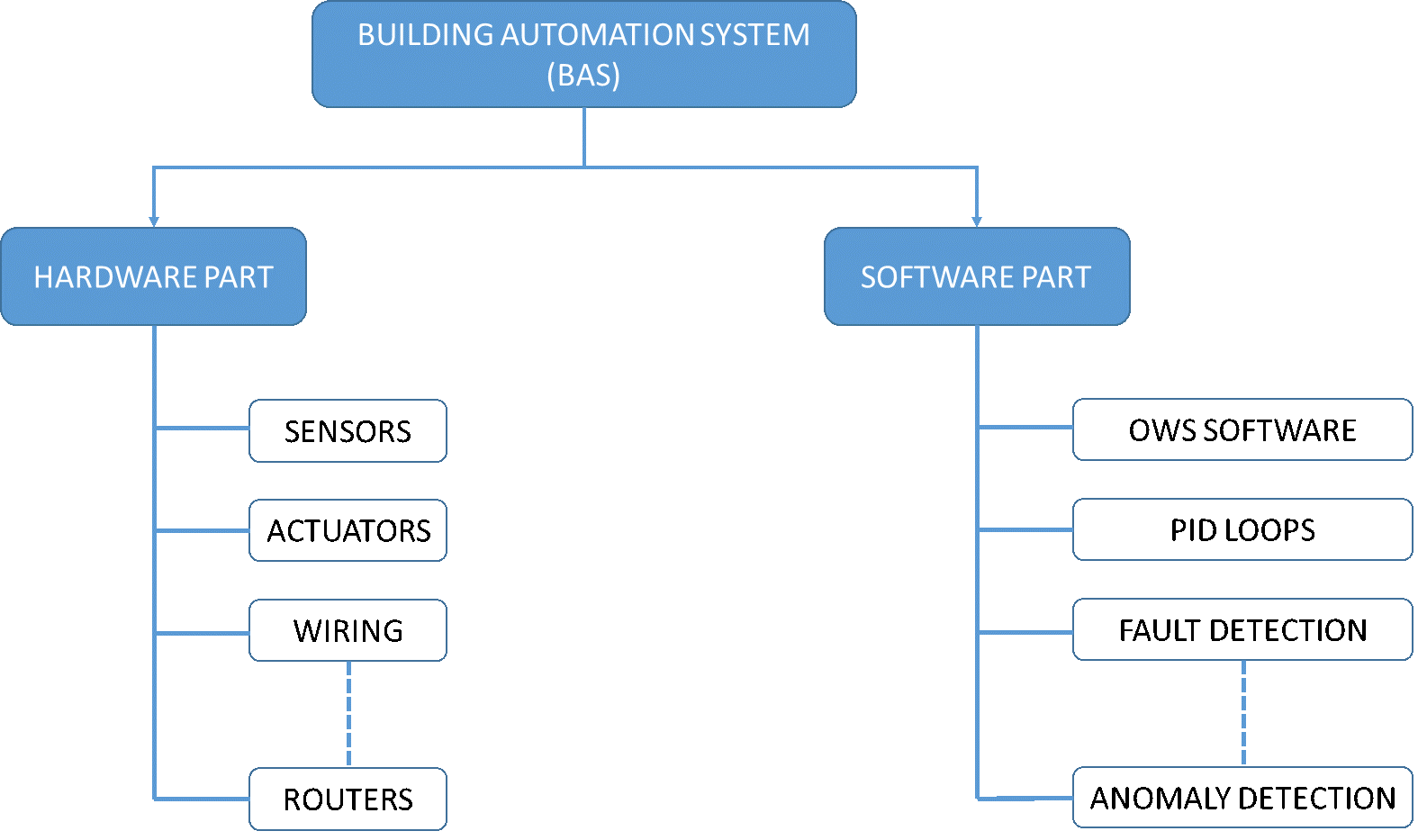
FIGURE 1. A summary of BAS components.
Illustrations courtesy of SmithGroup
As shown in Figure 1, the hardware portion of a BAS is composed of all physical components, including sensors, actuators, lighting switches, occupancy sensors, control devices, wiring, computers, routers, servers, Ethernet switches, and gateways. The software portion of the BAS is composed of all non-hardware elements and includes the programming of proportional integral derivative (PID) loops, the software that runs the control devices, the software that runs an operator’s workstation (OWS), the server, analytics, fault detection, and anomaly detection. Note, the server can be a hardware component and/or a software component and is, therefore, a critical component to properly design and specify to ensure the responsibilities of the contractor(s) are well understood.
Regardless of the quantity or type of hardware components, there must be a language these hardware components use to:
- Communicate with each other (e.g., temperature sensor to variable air volume [VAV] reheat valve); and
- Communicate with the user (e.g., sensors sending readings to the operator workstation).
This language is defined as a communication protocol. One of the most widely used communication protocols in the industry is BACnet, which stands for Building Automation and Control Network. The rules governing the BACnet communication protocol are defined in ANSI/ASHRAE Standard 135-2020, “BACnet: A Data Communication Protocol for Building Automation and Control Network.”
BACnet defines a series of (hardware) device profiles, as follows:
- BACnet advanced operator workstation software (B-AWS);
- Remote BACnet advanced operator workstation software (Remote B-AWS);
- Portable operator workstation software (Portable B-OWS);
- Building controllers (B-BC);
- Advanced application controllers (B-AAC);
- Application specific controllers (B-ASC);
- Smart sensor (SS); and
- Smart actuator (SA).
The B-BCs and B-AACs are typically used to control cooling and heating plants and large pieces of HVAC equipment, such as air-handling units (AHUs), that have a significant number of sensors, actuators, and relatively sophisticated sequences of operations. B-ASCs are typically used to control VAV boxes, fan coil units, fan-powered boxes, and other terminal equipment characterized by a limited number of control points.
The architecture of the BAS describes how the hardware components are arranged in the building. To understand this wiring road map, one must first comprehend the various BACnet communication protocols. The two most widely used BACnet communication protocols currently employed are BACnet IP and BACnet MS/TP.
The "IP" in the BACnet IP communication protocol stands for internet protocol. This means the devices that use this type of communication protocol are wired through Ethernet cables. The communication wiring (not to be confused with the wiring for power to the devices) is like the wiring used to network standard routers with PCs or laptops in a home or office environment.
Devices that use the BACnet MS/TP communication protocol are wired via RS-485 twisted-pair serial cabling daisy-chained (a wiring scheme in which multiple devices are wired together in sequence or in a ring that communicate signals through each device in a binary manner) into one network or multiple subnetworks, depending on the quantity of devices. The daisy chain can be seen on the FCU B-ASC in Figure 2. The "MS" in MS/TP stands for master/slave, while the "TP" stands for token passing. For the control devices to communicate using the MS/TP protocol, devices must take turns (passing a token) becoming a master, while other devices become slaves.
It's extremely important to note the communication speed between devices communicating over the BACnet IP protocol can support 100-MB-plus internet speeds, whereas the communication speed between devices communicating over BACnet MS/TP protocol typically has about 0.1 MB speed, at maximum. As the number of hardware components being controlled by a BAS increases, this speed differential may have a noticeable impact on the system response for critical processes. BAS speed is often an area where costs vary widely, and the benefits of improvements in performance need to be weighed by the owner.
Having determined the communication protocol, one must next understand the different types of potential network approaches that can be used to wire the hardware components of the BAS to define the system architecture. An ELCN typically consists of high-speed BACnet/IP local area networks (LAN) to host B-AWSs, B-BCs, BLCNs, and web-enabled remote connectivity. A BLCN shall consist of a BACnet internetwork to host field-level DDC controllers.
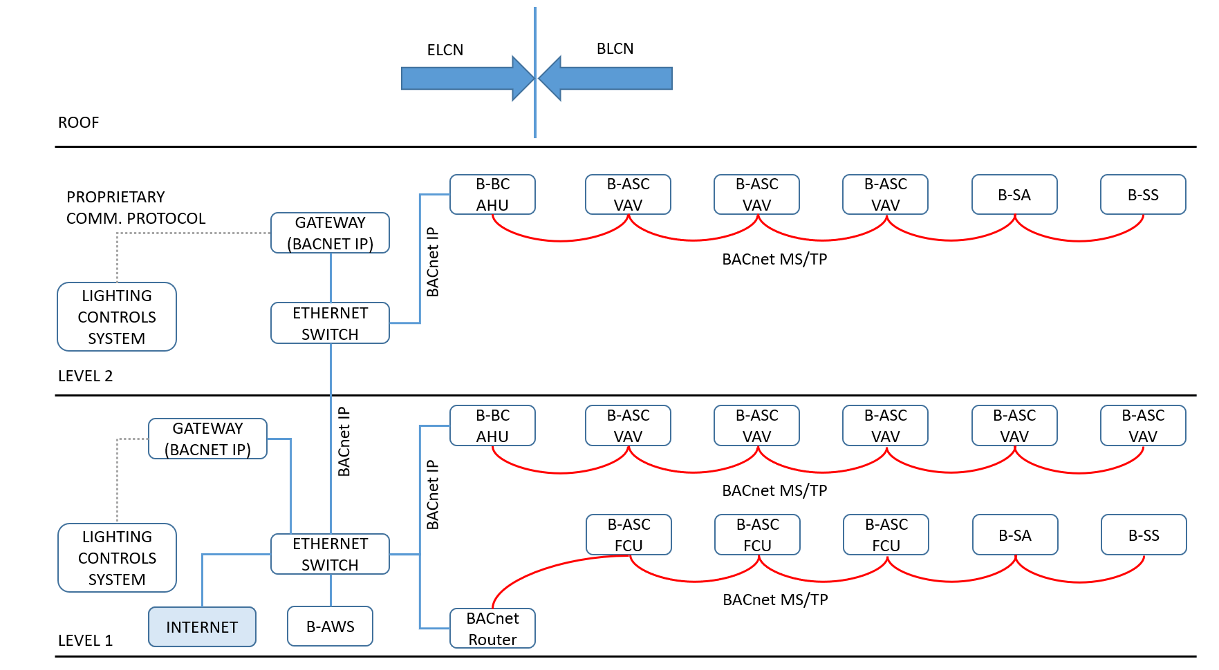
FIGURE 2: A sample BAS architecture using BACnet MS/TP and BACnet IP protocols.
A potential BACnet-based network architecture is shown in Figure 2. Typically, a B-BC is provided to control the main AHU serving the floor. B-ASCs are then provided to control all VAV boxes associated with that AHU. B-SSs and B-SAs can also be connected to the same MS/TP network used by the VAV boxes.
Lighting control systems are typically integrated into a BACnet-based BAS using BACnet gateways. The gateway acts as translators between the controllers within the lighting controls system and the BACnet-based BAS. This is required because, in most instances, lighting control systems use a proprietary (vendor specific) communication protocol (and not BACnet IP or MS/TP). The gateways are needed to translate the language of BACnet into the (proprietary) language used by the lighting control systems.
It's important to note the terms "gateway" and "routers" are not interchangeable. As previously described, gateways are translators that are used to join dissimilar systems. On the other hand, and as shown in Figure 2, routers are facilitators of communication. If devices use the same communication protocol (e.g., BACnet), the router forwards messages between the devices on the network. Lastly, a network switch is used to connect multiple devices and networks to expand the LAN.
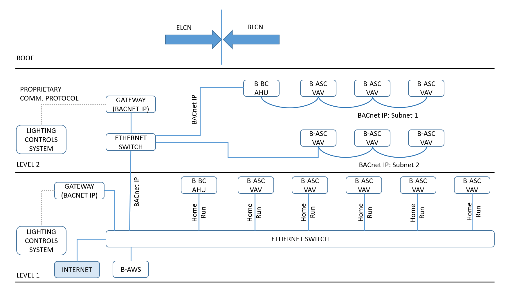
FIGURE 3. A sample BAS architecture using only the BACnet IP protocol.
The current industry trend, supported by some of the largest vendors in the controls industry, is for B-ASCs to come with the capability of being directly connected to the BACnet IP network. This eliminates the need for BACnet MS/TP communication protocol and the associated wiring. As shown in Figure 3, the B-ASCs can be wired in at least three configurations, with each architecture having its own pros and cons.
In the first configuration (BACnet IP: Subnet 1), the B-ASCs are daisy-chained together and through the associated AHU B-BC. The advantage to this approach is that the amount of Ethernet cable needed to connect all devices on the subnet is relatively short. One of the main risks associated with this approach is loss of communication; that's if the cable between any two devices is damaged and/or if one device has lost power, then the BAS will most likely lose communication with the devices located downstream of the device that has lost power.
To mitigate the risk of losing communication with as few devices as possible, another potential configuration is to divide the network into subnetworks; the devices on each subnetwork (BACnet IP: subnet 2) will then be daisy chained together and connected to the rest of the network(s) via switches. One of the cons of using this configuration is the need for additional Ethernet cable and the associated labor hours required for installation.
Relative to the first and second configuration, a more conservative third approach is to “home run” each device. This means an ethernet cable is run between the device and a central location (typically an IT room) that houses a series of switches. Although this approach minimizes the risk of losing communication with the devices, it is the most expensive method of designing and installing a BAS and requires the most physical space for cabling and switching.
The intent behind this article is to provide a foundation from which young engineers and contractors may begin to understand the terminology, components, and system architectures that are commonly used in the industry. When developing a BAS, it is within both the engineers’ and owners’ best interest to conduct a cost/benefit/risk analysis that can be vetted before proceeding with the design to establish a type of network architecture that best meets the needs of the building and the owners’ budget. Moreover, it would also be beneficial to incorporate the construction manager into the BAS conversation. This practice allows for expectations to be set early on the project regarding the BAS and the components necessary to deliver on the project requirements. With the engineer providing a breakdown of the BAS and the construction manager voicing his or her concerns or confirmations of the BAS design constructability and cost impact, the owner’s ability to interpret and act on the data becomes an important determinant in the design process.
Look for additional articles from SmithGroup on the topic of BAS architecture in the months to come. These will dive deeper into specific BAS components, protocols, and architectures, and how to implement them into a cohesive design.

Khaled Khalil
Khaled Khalil is a mechanical designer with SmithGroup in Washington, D.C. He recently joined SmithGroup after graduating from the Pennsylvania State University with a master’s degree in architectural engineering with a mechanical focus. He is gaining experience across a variety of project work and is particularly drawn to the unique process of control system development. He can be contacted at khaled.khalil@smithgroup.com.

Jamison Caldwell, P.E., LEED AP
Jamison Caldwell is mechanical engineering Principal with SmithGroup in Washington, D.C. He has more than 15 years of mechanical design experience. While primarily focused on science and technology projects within the higher education studio, Jamison also has experience in mission critical, healthcare and campus planning. He holds a bachelor’s degree in Mechanical Engineering from Lafayette College. He can be contacted at Jamison.caldwell@smithgroup.com.
Ionel Petrus, P.E., CEM, LEED AP BD+C
Ionel Petrus is a licensed professional engineer who has more than 13 years of mechanical design experience. In addition to being the mechanical discipline leader in SmithGroup’s Washington, D.C., office, he is also a LEED AP and a certified energy manager. His experience includes designing HVAC systems for commercial buildings, research laboratories, health care facilities, and museums. He can be contacted at ionel.petrus@smithgroup.com.

Video by Dimitris Christou from Pixabay