
SCROLL
COMMISSIONING
Commissioning Lead/Lag Pumping Operations: Part I, Identifying a Designer’s Intent
If a system was designed to operate in lead/lag, but lead/standby was implemented, it would not be able meet the flow requirements during the highest load periods.
I would like to thank Rebecca Ellis, P.E., for her 25 years’ worth of contributions to this publication. She has made, and continues to make, significant impacts on this industry, and I am grateful to be able to call her my boss, mentor, and friend. I am honored to be taking over this column.
When it comes to operating HVAC systems, there are many operational concepts that are widely accepted. And while the implementation of these concepts has been attempted over and over, I’m astonished by the number of pitfalls that prevent them from being successfully executed.
When it comes to HVAC operations, the devil lives in the details. To make sustainable impacts on the operation of the systems they work with, commissioning engineers cannot shy away from these details.
I will start with an examination of the lead/lag control strategy. This concept can apply to a variety of equipment that operates in parallel: pumps, fans, boiler, chillers, cooling towers, etc. This article will focus on variable-speed distribution pumps in hydronic systems.
Defining Lead/Lag
In a typical variable-speed hydronic system, the operating pump has its speed modulated to maintain adequate differential pressure in the system (see Figure 1). The flow requirements of a properly configured setup will track on the heating or cooling requirements of the system. For example, as outdoor air temperatures rise, the cooling requirements of the building, and thus the chilled water flow requirements, increase. If there are multiple, variable-speed distribution pumps piped in parallel, the range of flows experienced over the course of the year may vary enough that it makes sense to operate fewer pumps during periods of low load and only operate more pumps during periods of higher load. This can save energy and reduce wear on the pumps. Automated control systems can be configured to stage-on additional pumps when flow requirements increase as well as stage-off excess pumps when flow requirements decrease. When commissioning such a system, one must identify the designer’s intent prior to getting into the sequence of operation.

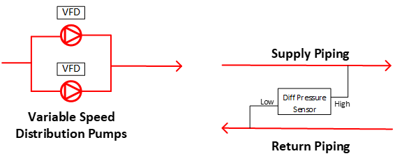
FIGURE 1: The pump speed is modulated to maintain system differential pressure.
Images courtesy of Questions & Solutions Engineering
Unless otherwise noted, all scenarios talked about in this series will assume there are only two pumps piped in parallel. The implementation of a successful lead/lag control strategy starts with recognizing when it's appropriate. Often, the design documents are not clear. In my experience, the leading reason for this is the rampant confusion in this industry between the terms “lead/lag” and “lead/standby.”
A lead/lag pumping configuration means the lead pump will operate continuously, but the lag pump will only operate in parallel when the lead pump can no longer efficiently meet the flow requirements of the system by itself. It also disables when the lag pump will disable when it's no longer needed. The designer has sized the pumps for partial redundancy, meaning all pumps are expected to be required during a design day.
A lead/standby pumping configuration implies the pumps are sized for full redundancy. Meaning, on the warmest day of the year, when flow requirements are at their peak, the lead chilled water pump will be able to meet the flow requirements of the system by itself. The standby pump would be enabled if the lead pump fails.
To be clear, the concept of a standby pump can and should be applied to a set of pumps sized for lead/lag as well. The building automation system (BAS) can be programmed so that when the lead pump fails, the lag pump is enabled to take its place.
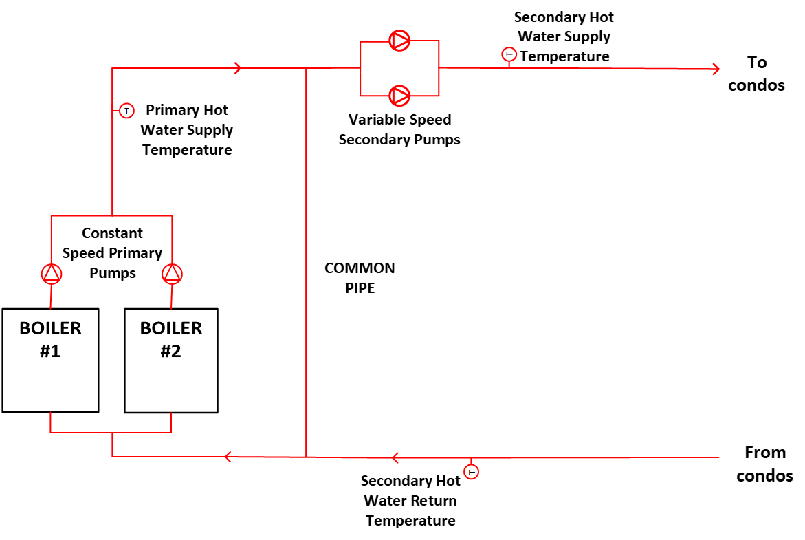
FIGURE 2: A constant-speed primary/variable-speed secondary hot water system.
Identifying the Correct Strategy
Due to the confusion between the terms "lead/lag" and "lead/standby," design documents, at times, do not clearly convey the designer’s intent. If a sequence of operation for the pumps is lacking, or possibly missing altogether, one may be able to infer the designer’s intention elsewhere.
For example, the pump schedule may have a note detailing the designed level of redundancy. If two secondary chilled water pumps were scheduled and a schedule note states, “sized for full redundancy,” then it's clear a lead/standby control sequence was intended.
One may be able to infer the designer’s intent from the scheduled flows as well. For example, if it's a primary/secondary pumping system, and the sum of the scheduled flow for the secondary pumps is double that of the sum of the primary pumps’, then, again, lead/standby for those secondary pumps can be inferred. Comparing the scheduled flows of served loads to the scheduled flow of the distribution pumps may provide insight to the designer’s intent as well.
Certainly, if the design engineer is available, ask him or her. However, this is not always a luxury one has when working with existing buildings.
Incorrect Sequences
Implementation of the incorrect sequence has consequences as outlined below:
Lead/standby incorrectly implemented: If a system was designed to operate in lead/lag, but lead/standby was implemented, then the system would not be able to meet the flow requirements during periods of the highest load. This scenario results in comfort issues and is often diagnosed quickly, as it is a relatively easy problem to troubleshoot.
Lead/lag incorrectly implemented: A high-rise condominium was unable to heat units above 55°F in the winter of 2019. The heating hot water system had a constant-speed primary/variable-speed secondary pumping configuration (see Figure 2). The served loads were getting a lower-than-designed temperature of hot water supplied to them. This was due to excess secondary flow, which exceeded the primary flow in the system. Water traveled opposite of the intended direction in the common pipe, and the secondary hot water supply temperature degraded. The root cause creating this situation was the inappropriate control of a makeup air unit1, but the fact the secondary pumps were set up with a lead/lag control sequence, despite being sized for a lead/standby configuration, only exacerbated an unstable situation by allowing the secondary flow to creep even higher.
Constant parallel operation: In 2021, our firm performed retro-commissioning on another high-rise condominium. It was only several years old, and the building had maintained a relationship with the design engineer. The secondary chilled water pumps were set up to both run in parallel continuously the entire year. Chilled water was always made available to residents, even in the cold months, by use of a free cooler. The design documents were clear that both pumps were needed during a design cooling load. We recommended to transition to a lead/lag control sequence to save energy and pump runtime during periods of low load. The designer’s position was that it was unnecessarily sophisticated and would result in minimal energy savings. During a building walk with the designer, we tested this theory. It was 46° outside, and the cooling load was minimal. We went to the two operating pumps’ variable frequency drives (VFDs), ensured they were stably maintaining the differential pressure set point on the BAS (i.e., meeting the flow demand of the building), and recorded the collective power use. We then killed power to one of the pumps. The remaining operational pump sped up slightly to again track on the differential pressure set point. Once the set point was stably maintained, we, again, recorded the power draw from the operational pump. The net power reduction was 39% for that moment in time. Conservative estimates for the building put the annual savings associated with implementing a lead/lag control sequence at $1,030, which resulted in less than a year payback.
Conclusion
Ensuring you understand the designer’s intent and how they sized the distribution pumps is a key step in commissioning such pumping operations. This article highlighted some of the issues that are experienced when the intent is unclear or misguided. Part II will look at the detailed sequence of operations and point out some items to look for in your reviews. Part III will finish by discussing the functional testing of lead/lag pumping operations and how to optimize their performance.
1Ryan, M. 2021. “Understanding Cascade Control and Its Applications for HVAC.” ASHRAE Journal (February).
Miles Ryan, P.E.
Miles Ryan is a commissioning engineer at Questions & Solutions Engineering. As a major in the Air Force Reserves, he serves as a mechanical systems instructor at the Air Force Institute of Technology. Contact him at miles.ryan@qseng.com.