

feature
Revit-izing the Ventilation Spreadsheet Workflow and Associated Calculations
The real power of BIM comes when the 'I,' or information, is fully utilized.
Building information modeling (BIM) is useful for its 3D coordination and ability to work within the same model as other disciplines, but the real power of BIM comes when the “I,” or information, is fully utilized.
Generally, a team’s time is better spent working on the design and technical challenges versus adding numbers or managing a model. The larger a project is, the more information it possesses, which can be time-consuming to manage. By using the model information and tools, such as Dynamo, a graphical programming tool, repetitive processes and calculations become more efficient, reduce errors, and improve the transfer of information from one step to another. This requires a deep understanding of the workflows and their intricate relationships.
“Smart schedules” might be what people first think of when they consider information, but we can get much more sophisticated. The following example was implemented for the New Valley Hospital in Paramus, New Jersey. The New Valley Hospital is a ground-up, 875,000-square-foot, 372 single-patient-bed hospital with 100% acuity adaptable rooms within three bed towers. The towers are connected by a diagnostic and treatment chassis and a 27,000-square-foot central utility plant and will provide a flexible facility design with universally sized operating and procedure rooms. This project had four models for mechanical and 12 models for mechanical, electrical, plumbing, and fire protection (MEPFP) disciplines. To be efficient and create consistency throughout the project, new workflows were implemented.
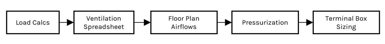
FIGURE 1: If information in one part of the process changes, the other processes can be impacted.
Photo courtesy of SmithGroup
The Big Idea
A mechanical engineer must complete load calculations to inform their ventilation calculations, which then informs their terminal box sizing and pressurization drawings. If information in one part of the process changes, the other processes can be impacted.
Typically, these processes are disconnected and include manual work. However, all this information can be integrated in the Revit MEP BIM and manipulated with Dynamo. Before getting into the details of a new workflow, it’s important to understand a typical workflow without fully utilizing BIM.
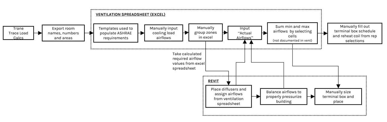
FIGURE 2: A typical BIM workflow.
A Typical Workflow
Load Calculations — Load calculations inform how much airflow is needed to cool each space and are done in a program, such as Trane Trace. Results are either manually input into a ventilation spreadsheet or exported to Excel and more easily transferred to the ventilation spreadsheet.
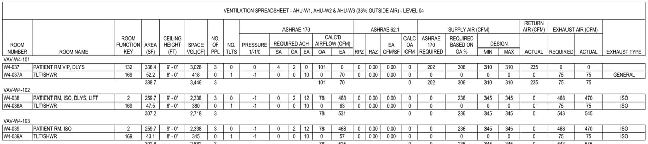
FIGURE 3: An example ventilation spreadsheet.
Ventilation Spreadsheet — The ventilation spreadsheet is built in Excel with lookup tables linking ASHRAE 170 and 62.1 requirements that are compared to the cooling load requirements by means of Excel formulas. The most stringent airflows are used as minimum baselines and manually applied to the registers, diffusers, and grilles on the floor plans within Revit MEP. Certain offsets of the supply air and return/exhaust air will be defined to ensure specific areas meet code mandated space requirements. The authority having jurisdiction (AHJ) will review the ventilation spreadsheet and floor plans to verify code requirements are met and values are consistent.
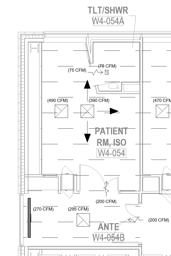
FIGURE 4: An example of pressurization.
Pressurization Drawings — ASHRAE 170 requires certain types of spaces to have specific pressure relationships with adjoining spaces. The AHJ requires pressurization drawings with arrows indicating how much airflow is being transferred and its direction. This can be a tedious process as it requires manually reviewing each space and the surrounding airflows. If an airflow changes at some point in the design process, which it will, it may impact and change all the adjoining space relationships.
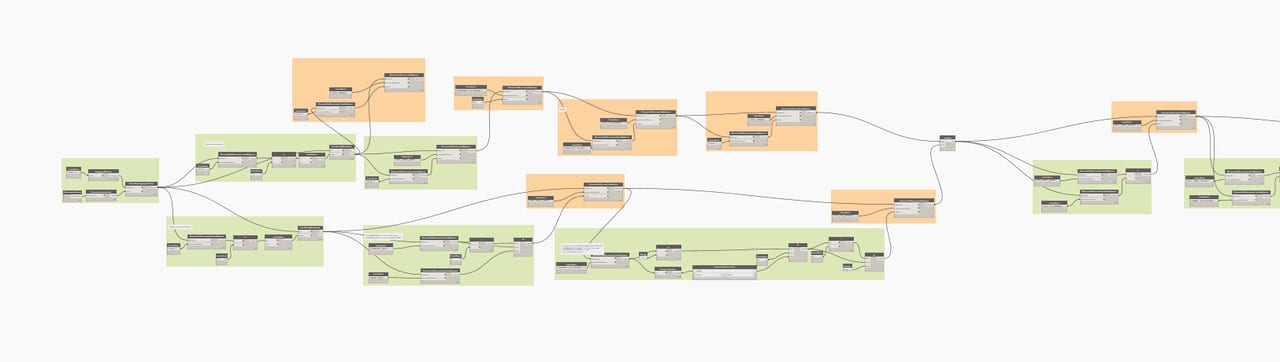
FIGURE 5: A partial view of a Dynamo script.
Terminal Boxes — When using a VAV system, each zone will have a terminal box serving it. The ventilation spreadsheet minimum and maximum airflows are summed for all of the spaces within the zone and define the terminal box minimum turndown and maximum airflow. From there, the terminal box size and reheat airflow is determined. For large projects, this information can be sent to an equipment representative who will send coil selections that will be translated to the Revit schedules.
The New Workflow
All the information required to complete calculations are (or could be) in the Revit model and able to be read by the Revit Space object. Spaces are volumes that are placed in the MEP model where the architectural room objects are. The new workflow utilizes the space that reads all the information assigned to it to calculate and tie the various steps together.
Load Calculations — The information is still exported to Excel from Trane Trace, but now a dynamo script is used to read the information from Excel and write it to the Revit Space with the push of a button. This takes out the manual work of having to input the values into the Revit schedule or another Excel each time there is a change.
Improvements from a typical workflow:
- No manual translation of bulk data and less room for error; and
- Time saved.
Ventilation Spreadsheet — Dynamo is used to complete the following:
- ASHRAE 170 airflow calculations and requirements;
- ASHRAE 62.1 airflow calculations and requirements;
- Compare ASHRAE, Trace load airflows, and any manual override values to determine final required airflow;
- Compare the minimum turndown ratio of all spaces within a zone and what is the controlling turn down ratio for usage in terminal box sizing; and
- Output/read the airflow that is on the floor plan views serving each space.
Improvements from a typical workflow:
- Less room for error with people modifying formulas and/or not realizing there were formulas overwritten in an Excel spreadsheet;
- More accurate calculation for turndown of space; and
- Time saved not having to manually translate airflow on floor plans to ventilation spreadsheet.
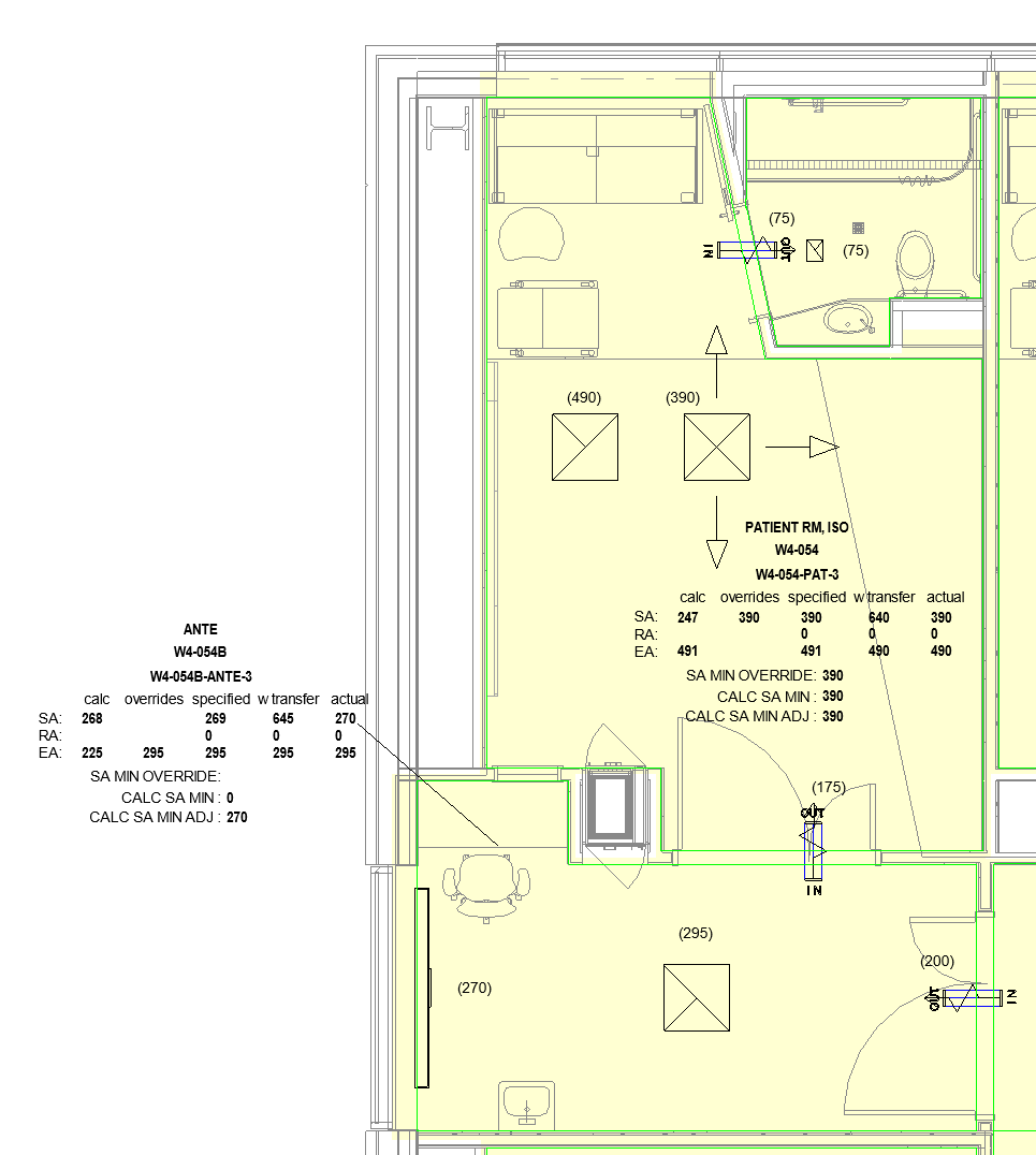
FIGURE 6: An example of color fill for properly pressurized spaces.
Pressurization Drawings — Transfer ducts with grilles are placed between each space that has a pressure differential. Dynamo is used to:
- Calculate the air that is being transferred between spaces and assigning to the transfer duct; and
- Place transfer arrows on top of the transfer ducts.
The transfer ducts are only viewable in working views and are not seen on printed drawings. The arrows are only shown on the specific pressurization drawings and are tagged with the airflow transferred.
There is also a working view set up to graphically show the pressurization has been properly calculated. If all pressurization has been calculated, the spaces should show as light yellow. If a space is still being shown as negative (red) or positive (green), transfer arrows have not been placed.
Improvement from a typical workflow:
- Less room for error with manual calculation mistakes;
- Graphical confirmation pressurization is calculated accurately; and
- Time saved not having to manually calculate transfer air every time an airflow changes.
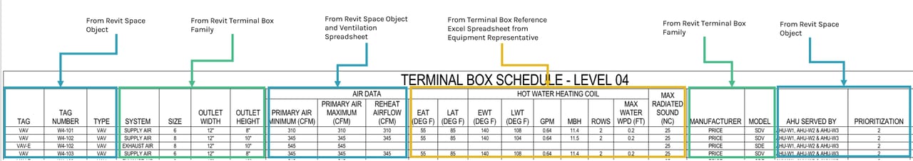
FIGURE 7: Terminal box schedule information sources.
Terminal Boxes — The Revit Spaces are zoned together, and the zone is named the same as the terminal box serving it. At the start of this project, a range of airflows and terminal box sizes were sent to an equipment representative to get a range of terminal box reheat coil sizing in an Excel spreadsheet.
Dynamo is used to:
1. Group spaces by the zone number.
2. Assign the terminal box maximum airflow by:
a. Adding up airflows assigned to diffusers, registers, and grilles within space; and
b. Assigning total airflow as the maximum airflow for the terminal box.
3. Assign the terminal box minimum airflow by:
a. Adding up minimum ASHRAE airflow requirements and compare to 30% of the box minimum; and
b. Assigning the greater of the airflows as the minimum terminal box airflow.
4. Assign the reheat airflow (as required) by:
a. Comparing minimum airflow and one half of the maximum airflow; and
b. Assigning the greater of the airflows as the reheat airflow.
5. Reference the Excel reheat coil sizing spreadsheet from the equipment representative and add information to Revit terminal box for scheduling.
Improvement from a typical workflow:
- Less room for error with manual calculation mistakes;
- Time saved not having to manually add up airflows;
- Less back and forth with an equipment representative and/or using terminal box sizing software each time airflows changed; and
- No manual schedule data input.
Benefits of New Workflow
Below is a summary of the main benefits of the new workflow compared to the typical workflow:
- Removes manual calculations and errors;
- Creates consistency with calculations;
- Best for large amounts of data;
- Can be used to recalculate easily;
- Allows for data inputs directly in Revit versus creating images of Excel documents;
- Creates consistency between multiple models/building data; and
- Saves time.
Lessons Learned
Although there are some benefits of using this new workflow, there are lessons learned and areas of improvement:
- Implementing a new workflow requires gradual training for all users and in-depth documentation;
- A more Revit-ized workflow may be more difficult for some of the more experienced engineers to review/manipulate if they do not typically work in Revit;
- New situations arise with new workflows, and the project team needs to be adaptable and agile to react; and
- The workflow may need to adapt at various phases of the project. For example, in the design development or construction documents phase, you may want to run calculations for all or many spaces while in construction administration, or you may only want to run calculations on specific spaces.
Would the team use this workflow again? Yes and no. Without this workflow, the scale of this project would require a larger team to manage all the repetitive calculations and data input. Being this was the first time we utilized this workflow, there is a lot of room for improvement. The team is working on optimizing the workflow to fit various project sizes and types to meet all needs of the project and project team.

Jessica Vines, P.E., LEED AP BD+C
Jessica Vines is a mechanical engineer at SmithGroup.
Image courtesy of HDR (www.hdrinc.com)